EM273 and PCM4222:
Maximum level:
EM273: 4.4934 V peak-peak in its standard application circuit, see post #71, https://www.diyaudio.com/forums/dig...-fixed-gain-field-recorder-8.html#post6690262
PCM4222: 5.6 V peak-peak (differential, so 2.8 V peak-peak per pin)
Hence, maximum allowed gain if you don't want to reduce the 135 dB SPL maximum level:
5.6 V/4.4934 V ~= 1.2463
Noise:
A-weighted noise of the PCM4222: 124 dB below the maximum sine wave level when you use the multibit modulator output, like TNT wants to do
5.6 V peak-peak sine wave -> 1.9799 V RMS -> noise level 1.2492 uV A-weighted
Noise of the EM273:
14 dB(A), or 80 dB A-weighted below 1 Pa
Sensitivity -37 dB with respect to 1 V/Pa, so 14.125 mV/Pa
Hence, the noise is 1.4125 uV A-weighted
When you allow the ADC to produce as much noise as the capsule, which will lead to a 3.01 dB degradation (amplifier between microphone and ADC neglected):
Minimum gain for 3.01 dB noise floor increase: 1.2492 uV/1.4125 uV ~= 0.8844
For 1 dB rather than 3.01 dB noise floor increase:
extra gain needed of 1/sqrt(10^(1/10) - 1)
Minimum gain for 1 dB noise floor increase: (1/sqrt(10^(1/10) - 1))*1.2492 uV/1.4125 uV ~= 1.738
By the way, most of the noise of the PCM4222 is very probably plain old analogue circuit noise. It is much more difficult and expensive in terms of current and chip area to reduce analogue circuit noise than to reduce shaped quantization noise.
By the way, you can increase the gain of the evaluation board by reducing R9, R10, R11 and R12.
Ignoring your requirement of not using AC coupling capacitors, the simplest way to get close to a gain of 1.2463 would be to reduce R9, R10, R11 and R12 on the evaluation board to 220 ohm or 221 ohm. You could then drive the inputs single-endedly using the standard microphone application, some voltage follower and big AC coupling capacitors. The negative inputs would have to be grounded through equally large capacitors.
The input resistance with single-ended drive would be 303.66 ohm when R9, R10, R11 and R12 are reduced to 220 ohm, so 100 uF electrolytic capacitors (preferably bipolar for minimum capacitor distortion) would give you a cut-off frequency of about 5.24 Hz. The voltage follower would have to be able to deliver a peak output current of 7.4 mA, so it could either be some op-amp voltage follower or an emitter follower that's biased at 10 mA or so using a current source - if you can find the voltage headroom for an emitter follower and current source.
Last edited:
Thanks all!
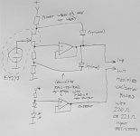
So I interpret that using fig10 it would be end up the picture below?
Marcel - that would be a way to do it for sure. I think I would use an OP-AMP of latest sort to do that impedance shift. Gain here or gain there? Sameo-samo?
But yes - I would have liked to not using serial caps.
//
So I interpret that using fig10 it would be end up the picture below?
Marcel - that would be a way to do it for sure. I think I would use an OP-AMP of latest sort to do that impedance shift. Gain here or gain there? Sameo-samo?
But yes - I would have liked to not using serial caps.
//
Attachments
EM273 and PCM4222:
Maximum level:
EM273: 4.4934 V peak-peak in its standard application circuit, see post #71,.....
Thanks for the calculations Marcel - interesting is that it seems like it is in the ball-park as is. Lucky strike...
Use a 1:1 buffer +try get rid of the caps somehow and... try it out. Maybe it needs to go up or down 10 dB... or even a switch in the end to change say 10-15 dB to adapt to recording situation (low/high)
//
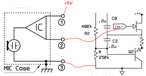
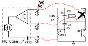
The FET is inside the EM273 capsule, see the modified picture.
Regarding the AC coupling capacitors: as long as the DC voltage at the output of the buffer is not too far from the common-mode voltage of the differential amplifier on the evaluation board, you can in principle make some sort of voltage source with about the same voltage, connect that to the negative input and leave out the capacitors. Offsets up to 200 mV or so (<< the peak microphone output voltage at 135 dB) are OK when you apply a digital high-pass somewhere.
Regarding the AC coupling capacitors: as long as the DC voltage at the output of the buffer is not too far from the common-mode voltage of the differential amplifier on the evaluation board, you can in principle make some sort of voltage source with about the same voltage, connect that to the negative input and leave out the capacitors. Offsets up to 200 mV or so (<< the peak microphone output voltage at 135 dB) are OK when you apply a digital high-pass somewhere.
Attachments
Last edited:
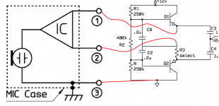
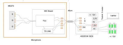
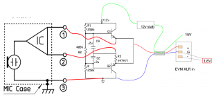
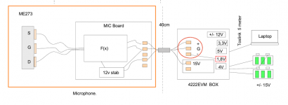
OK - so:
Is there a smart way of making this differential out as these will be 40-50 cm cable...
The red lines drawn is planned to be in the capsule case...
Function distribution as in post #99
haha - but now I realise I'm not really trough with the function packaging and interface definitions..
I'll be back :-D
//
Attachments
Last edited:
Regarding the AC coupling capacitors: as long as the DC voltage at the output of the buffer is not too far from the common-mode voltage of the differential amplifier on the evaluation board, you can in principle make some sort of voltage source with about the same voltage, connect that to the negative input and leave out the capacitors. Offsets up to 200 mV or so (<< the peak microphone output voltage at 135 dB) are OK when you apply a digital high-pass somewhere.
OK - cool - I need to draw this... but now of to the yearly dentist appointment
")
//
How is this to be changed - I just can't short C3 & C4... can I?
//
No you can't. Note the Max SPL on the data sheet is using the 5V supply and the standard circuits. This circuit does much more.
In either case I don't see the worry about max SPL is a real recording application, data I've seen showed 115dB peaks in the third row of a full orchestra. As I said I've already done this with an EM23 at a built in gain of 11 (110dB/PA) which would do nature field recordings as well as live music where the only clipping was an enthusiastic fan clapping as loud as they could in the next seat.
Yes, probably 115 dB is enough upper limit. 120 would give peace at heart.
Scott, is it possible to get rid of the series caps somehow?
//
You just end up with a unity gain source follower. I'm used to working with field recorders and sound cards with built in pre-amp circuitry and phantom power that get in the way between the mic and A/D so I have no idea how well directly into the A/D can work. The 14dB or so noise is probably good enough for most general purpose use but I would check on the distortion characteristics of the mic at these high SPL's without the bootstrapping.
"Simple". Intersting. I wish I could do an insightful analysis of these circuits - but alas...
https://www.analog.com/media/en/technical-documentation/data-sheets/1677fa.pdf ?
//
https://www.analog.com/media/en/technical-documentation/data-sheets/1677fa.pdf ?
//
Wiki: "In the field of electronics, a bootstrap circuit is one where part of the output of an amplifier stage is applied to the input, so as to alter the input impedance of the amplifier. When applied deliberately, the intention is usually to increase rather than decrease the impedance.[1] Generally, any technique where part of the output of a system is used at startup is described as bootstrapping."
Sounds like NFB but I suppose its not the same thing...
//
Sounds like NFB but I suppose its not the same thing...
//
- Home
- Source & Line
- Digital Line Level
- Fixed gain field recorder?