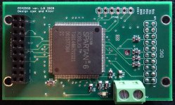
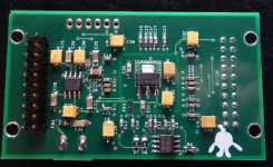
It's nice to present this project - separate delta sigma modulator for a dsc2 dac.
Special thanks to Jussi and Pavel.
The basic idea is to convert pcm to a dsd stream without the use of a PC.
Design flow goes as follows:
i2s serial data is converted to parallel, next we have the first interpolation fir filter,
in this filter the data is oversampled x2, x4 or x8 - this depends on the incoming data rate.
(for 44.1kHz we have x8 interpolation, for 96kHz x4 and for 192kHz x2)
next, the data is going to the two stage CIC filter and is oversampled x32 to final x256
Then the data is going into the sigma delta 7 order modulator, which has classical CRFB structure,
as I said earlier all arithmetics are done in CSD arith, so no multipliers here.
all coefficients are carefully optimized using delsig package
If someone asks, yes, there are g0, g1, g2 coeffs.
At the end the dsd streams are time aligned using ODDR2 primitives
XC6SLX9 is almost full, so there is no ability to add anything")
The device was designed to run with a mclk of 22/24 MHz.
To upload the attached bitstream file to the board you need a Xilinx programmer cable and Xilinx program Impact.
In the next post my friend PJotr will post gerber files, BOM and some measurements.
I hope this project will be interesting for someone.
DIY use only!
--------------------------------------------------------------------------------------------------------------------------------------------------------
Update 24.07.2023 New firmware !
First of all, I'd like to thank Markw4 for your help!
The entire software is practically completely new.
The first FIR filter now has x8 fixed interpolation (fs 44.1kHz - 192kHz), has 2048 taps, 32 bit coefficients and 100dB stopband attenuation.
Then it's a two-stage CIC filter and it's oversampled to the final x256. Oversampling depends on the rate of incoming data.
Then we have a 5-order sigma delta modulator, which has classical CRFB structure, with noise shaping and dithering.
And as before, at the end the dsd streams are time aligned using ODDR2 primitives.
We made tens of different firmware configurations and finally chose this version after listening sessions.
Latest firmware:
https://www.diyaudio.com/community/threads/simple-dsd-modulator-for-dsc2.370177/page-42#post-7407495
Special thanks to Jussi and Pavel.
The basic idea is to convert pcm to a dsd stream without the use of a PC.
Design flow goes as follows:
i2s serial data is converted to parallel, next we have the first interpolation fir filter,
in this filter the data is oversampled x2, x4 or x8 - this depends on the incoming data rate.
(for 44.1kHz we have x8 interpolation, for 96kHz x4 and for 192kHz x2)
next, the data is going to the two stage CIC filter and is oversampled x32 to final x256
Then the data is going into the sigma delta 7 order modulator, which has classical CRFB structure,
as I said earlier all arithmetics are done in CSD arith, so no multipliers here.
all coefficients are carefully optimized using delsig package
If someone asks, yes, there are g0, g1, g2 coeffs.
At the end the dsd streams are time aligned using ODDR2 primitives
XC6SLX9 is almost full, so there is no ability to add anything
The device was designed to run with a mclk of 22/24 MHz.
To upload the attached bitstream file to the board you need a Xilinx programmer cable and Xilinx program Impact.
In the next post my friend PJotr will post gerber files, BOM and some measurements.
I hope this project will be interesting for someone.
DIY use only!
--------------------------------------------------------------------------------------------------------------------------------------------------------
Update 24.07.2023 New firmware !
First of all, I'd like to thank Markw4 for your help!
The entire software is practically completely new.
The first FIR filter now has x8 fixed interpolation (fs 44.1kHz - 192kHz), has 2048 taps, 32 bit coefficients and 100dB stopband attenuation.
Then it's a two-stage CIC filter and it's oversampled to the final x256. Oversampling depends on the rate of incoming data.
Then we have a 5-order sigma delta modulator, which has classical CRFB structure, with noise shaping and dithering.
And as before, at the end the dsd streams are time aligned using ODDR2 primitives.
We made tens of different firmware configurations and finally chose this version after listening sessions.
Latest firmware:
https://www.diyaudio.com/community/threads/simple-dsd-modulator-for-dsc2.370177/page-42#post-7407495
Attachments
Last edited:
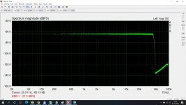
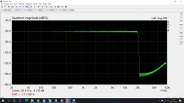
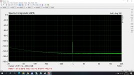
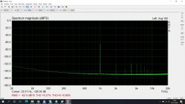
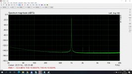
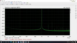
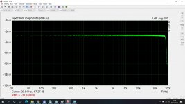
And now some measurements.
4 pic with THD for signal 0dB, -10dB, -60dB and -100dB.
3 pic with band of this modulator for input signal 44.1kHz, 96kHz and 192kHz.
These measurements are with DSC 2.5.2 (thanks to Jussi and Pavel).
4 pic with THD for signal 0dB, -10dB, -60dB and -100dB.
3 pic with band of this modulator for input signal 44.1kHz, 96kHz and 192kHz.
These measurements are with DSC 2.5.2 (thanks to Jussi and Pavel).
Attachments
Last edited:
I hope this project will be interesting for someone.
I'm excited! Super happy!
Looks as though you've already taken the plunge gionag - will you use it with your DSD Stick? - good luck and please let us know how it goes.
i have already ordered the pcb, the programmer, and i have the bom adapted and loaded to the cart.
I was waiting for a thing like this for long time... and i am eager to experiement.
surely it will get in the st!ck chain.
I will report the results

one note, i was unable to source the flash memory
Eg. look at ebay:
M25P80-VMW6G FLASH MEMORY, 8MBIT STMicroelectronics [QYT=2 PCS] | eBay
M25P80VMW6G SemiConductor - CASE: SO8 MAKE: NUM | eBay
It's nice to present this project - separate delta sigma modulator for a dsc2 dac.
Special thanks to Jussi and Pavel.
The basic idea is to convert pcm to a dsd stream without the use of a PC.
Design flow goes as follows:
i2s serial data is converted to parallel, next we have the first interpolation fir filter,
in this filter the data is oversampled x2, x4 or x8 - this depends on the incoming data rate.
(for 44.1kHz we have x8 interpolation, for 96kHz x4 and for 192kHz x2)
next, the data is going to the two stage CIC filter and is oversampled x32 to final x256
Then the data is going into the sigma delta 7 order modulator, which has classical CRFB structure,
as I said earlier all arithmetics are done in CSD arith, so no multipliers here.
all coefficients are carefully optimized using delsig package
If someone asks, yes, there are g0, g1, g2 coeffs.
At the end the dsd streams are time aligned using ODDR2 primitives
XC6SLX9 is almost full, so there is no ability to add anything
DIY use only!
Exciting project. Could you clarify CSD arithmetic in detail or reference paper? I can understand what you mean; xc6slx9 is at max capacity. Two x256 upsampling FIRs occupy almost everything. It's beyond my imagination why the rest can calculate two 7th order DSM with three local FBs(g0,g1, and g2) though I think two is enough for 7th order, IMO
. The only answer is probably CSD.Just thinking out loud for now; as always, my main concern with this type of project is the smd soldering and I'm wondering if a group buy for assembled boards might be a possibility. First things first though - Olek and Pjotr, what are your thoughts on this possibility?
Cheers
Cheers
Exciting project. Could you clarify CSD arithmetic in detail or reference paper? I can understand what you mean; xc6slx9 is at max capacity. Two x256 upsampling FIRs occupy almost everything. It's beyond my imagination why the rest can calculate two 7th order DSM with three local FBs(g0,g1, and g2) though I think two is enough for 7th order, IMO
Hi xx3stksm!
As they say, a picture is worth a thousand words, I send you complete list of coeffs and modulator vhdl code.
The code is without reset and dither for clarify.
You can easily check how it is done.
Olek
That partly answers my question before I even asked it: what did you do against idle tones? Apparently you used dithering, presumably partial dithering because 2 LSB peak-peak triangular PDF dither is impossible in a single-bit sigma-delta. Did you use any other tricks, like chaos or small DC offsets to shift the frequency difference between the tones just above and just below fs/2 out of the audio band? Whatever you did must be quite effective, as the spectra in post #3 show no sign of any idle tones, not even with a -100 dB desired signal.
Last edited:
Just thinking out loud for now; as always, my main concern with this type of project is the smd soldering and I'm wondering if a group buy for assembled boards might be a possibility. First things first though - Olek and Pjotr, what are your thoughts on this possibility?
Cheers
No problem, you just need to find someone to take care of it.
That partly answers my question before I even asked it: what did you do against idle tones? Apparently you used dithering, presumably partial dithering because 2 LSB peak-peak triangular PDF dither is impossible in a single-bit sigma-delta. Did you use any other tricks, like chaos or small DC offsets to shift the frequency difference between the tones just above and just below fs/2 out of the audio band? Whatever you did must be quite effective, as the spectra in post #3 show no sign of any idle tones, not even with a -100 dB desired signal.
Hi Marcel
I tried to use chaos which I like very much, but it couldn't fit into xc6slx9.
Finally I'm using dynamic partial dithering. The dithering levels were chosen experimentally because I don't know how to calculate them correctly yet.
As far as I know, everyone determines the dithering level for a single-bit sigma-delta experimentally, because dither theory only applies when you have more quantization levels available.
For chaos, you just need to choose your coefficients such that the loop filter becomes unstable while the whole sigma-delta does not. Why does that cost extra FPGA resources?
In the chaotic mode of the sigma-delta of my valve DAC, I put one z-domain pole of the loop filter a bit above +1 and one a bit below -1. Lars Risbo recommends that in his PhD thesis, stating that the pole below -1 destabilizes the idle tones around fs/2.
It didn't actually work that well: when I played silence in the chaotic mode at a very high volume, I got this woosh-woosh-woosh sound. It turns out that instead of a tone at a frequency proportional to the absolute value of the input signal, I now get amplitude modulation of the noise at a frequency proportional to the absolute value of the input signal. In the LX45 version I just added a DC offset as a workaround, the noise modulation during silence is now so fast that you don't notice it.
- Home
- Source & Line
- Digital Line Level
- Simple DSD modulator for DSC2