Not quite sure where to put this since it ticks the boxes for so many categories, but why not this one? ")
Ongoing build thread for my Aurora-based "everything" box. This will contain, at the very least, the following devices:
- freeDSP Aurora
- Mean Well RPS-30-7.5
- (2x) TPA3255EVM
- (TBD) (2x) TICore260BTL
- Connex SMPS800RS
The intended use is for the Aurora to act as a USB sound card in my PC so that I can feed a stereo 4-way monitor setup.
The chassis for this build is of a clamshell style, comprised of two Fat Daddio 16"x12"x3" anodized aluminum rectangular cake pans. Since the material is aluminum and not too thick, the casework is relatively pleasant, though I must admit that the sides can distort as the aluminum is not particularly strong. In any case, I don't regret going down this route... at least, not yet.
First photo shows some of the layout work. At this point I had already mounted the power entry module and two power switches (1 for the Aurora power supply and 1 for the amp power supply). Those went pretty easily with a Dremel with abrasive cutting disc and a rectangular file. As for the the actual photo, I CADed the mounting hole layouts for the PCBs, printed them onto paper, and taped them to the pan so that I could punch the centers. Here is where I realized that my printer is not particularly accurate; on a ~140 mm span (I think lengthwise on the paper) the printed center-to-center distance is about 0.5-0.75 mm longer than what drawing calls for. Good thing I checked before I ended up with useless holes! My first solution was to score the paper with my digital calipers fixed to the correct distances, but eventually I just resorted to laying the PCB on the paper and then tracing out the insides of the mounting holes using a mechanical pencil. This actually worked surprisingly well, so much so that in the future I'll probably do away with the CAD & paper.
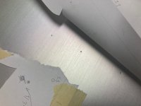
Second photo shows the marks from a Flexbar optical center punch. Love this thing. Not quite perfect (mainly an ergonomics thing) but it definitely makes quick work of punching accurate centers. One of the optical sight guides they provide with the unit has a sighting circle that pretty much lined up perfectly with the pencil-traced circles I drew beforehand, so if I had to guess, the accuracy of the punch marks is probably better than +/- 0.2 mm assuming perfect "centricity" on the included Flexbar optics and center punches.
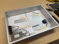
Third photo shows the PCBs in place. I was expecting everything to fall into place, but it's still a relief when it actually does. Any guesses as to what the drawer pull and the as-yet-unused 1/4" bolts around the perimeter are for?
First photo shows some of the layout work. At this point I had already mounted the power entry module and two power switches (1 for the Aurora power supply and 1 for the amp power supply). Those went pretty easily with a Dremel with abrasive cutting disc and a rectangular file. As for the the actual photo, I CADed the mounting hole layouts for the PCBs, printed them onto paper, and taped them to the pan so that I could punch the centers. Here is where I realized that my printer is not particularly accurate; on a ~140 mm span (I think lengthwise on the paper) the printed center-to-center distance is about 0.5-0.75 mm longer than what drawing calls for. Good thing I checked before I ended up with useless holes! My first solution was to score the paper with my digital calipers fixed to the correct distances, but eventually I just resorted to laying the PCB on the paper and then tracing out the insides of the mounting holes using a mechanical pencil. This actually worked surprisingly well, so much so that in the future I'll probably do away with the CAD & paper.
Second photo shows the marks from a Flexbar optical center punch. Love this thing. Not quite perfect (mainly an ergonomics thing) but it definitely makes quick work of punching accurate centers. One of the optical sight guides they provide with the unit has a sighting circle that pretty much lined up perfectly with the pencil-traced circles I drew beforehand, so if I had to guess, the accuracy of the punch marks is probably better than +/- 0.2 mm assuming perfect "centricity" on the included Flexbar optics and center punches.
Third photo shows the PCBs in place. I was expecting everything to fall into place, but it's still a relief when it actually does. Any guesses as to what the drawer pull and the as-yet-unused 1/4" bolts around the perimeter are for?
Attachments
Last edited:
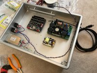
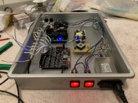
Plugged in power for the first time today. Feels pretty nice. Got a nice blue light out of the RPS-30-7.5, although I didn't connect power to the SMPS800RS; the earth connection to that isn't made properly yet as I'm still working on the GLB circuit for it. Gotta get that going and then I will boot up the Aurora and SMPS800RS for the first time.
Note: I hate using standoffs with male end(s). I must've wasted over 5 minutes just trying to tighten nuts onto one single PCB to secure it. I finally managed to do it but then later decided to replace the standoffs with ones that have female ends on both, so that I can use screws instead of nuts.
Note: I hate using standoffs with male end(s). I must've wasted over 5 minutes just trying to tighten nuts onto one single PCB to secure it. I finally managed to do it but then later decided to replace the standoffs with ones that have female ends on both, so that I can use screws instead of nuts.
Last edited:
Pretty lights! Managed to finish off the GLB board. Got everything powered up and updated the firmware on the Aurora to the latest.
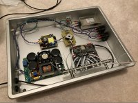
Not really looking forward to doing the wiring on 8 balanced outputs but it's got to be done. Will be starting the casework for the TPA3255EVMs soon.
Not really looking forward to doing the wiring on 8 balanced outputs but it's got to be done. Will be starting the casework for the TPA3255EVMs soon.
Attachments
Last edited:
Actually, before I start the casework for the TPA3255EVM modules I need to replace the analog input headers. Amongst other very-questionable decisions made by TI on this unit, the pins on the analog input headers are tin-plated; they are actually the only ones on the board that aren't plated in gold. So, I'm going to do that as well as replace the bulk caps with much smaller ones. Since I'm powering a bunch of modules from the SMPS800RS which has a manufacturer-recommended limit on load capacitance < 10 mF, I'm going to replace the stock 2x4700 uF caps on each module with 2x1000 uF 200 V. The higher voltage forces a bigger cap size which allows for higher ripple current rating.
Replaced the analog input headers with ones having gold-plated posts. Job went quite a bit tougher than I expected, mainly owing to the fact that the solder pads on the TPA3255EVM are fricking tiny, and also that the thermal reliefs on the ground pads don't do much to relieve the massive heat suckout. To their credit, though, the PCBs held up quite well to way too many heat cycles on those pads without any real damage (solder mask got marked up since my iron tip was too fat).
Didn't have enough time to do the bulk caps but will get to that in the next few days.
Didn't have enough time to do the bulk caps but will get to that in the next few days.
Last edited:
- Status
- This old topic is closed. If you want to reopen this topic, contact a moderator using the "Report Post" button.
- Home
- Source & Line
- Digital Line Level
- freeDSP Aurora-based USB 8-channel DSP/DAC/Preamp/Amp Build