A possible scenario of NOS self cancellation leaving pure OS at the output is if the original OS and NOS are not aligned after all... Maybe this explains the strange graph at the INA output? It shouldn't but those bumps should not exist even in the good scenario I think...
EDIT: Scenario is valid only for antiphase NOS and OS. Anything between should not give the measured magnitudes. Bumps still not explained. Output signal should be in opposite phase wrt the "expected".
EDIT: Scenario is valid only for antiphase NOS and OS. Anything between should not give the measured magnitudes. Bumps still not explained. Output signal should be in opposite phase wrt the "expected".
Last edited:
Summarizing, the final signal could be pure OS only if OS and NOS at the INA input are in opposite phase. That's the only condition to fulfill the measured equal levels of NOS, OS and "Hybrid" signals. If this was true, the output of the INA should give the sum of OS and NOS, more or less a signal double the level of the sources. But I'm not measuring such levels at the INA output. So, all evidence so far support the original concept.
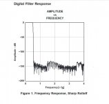
Attached is a typical digital filter frequency response of PCM1794 from the datasheet. Those bumps are very similar to what I captured where it was supposed to see silence. Could some kind of interference project them to the audio band?
Attached is a typical digital filter frequency response of PCM1794 from the datasheet. Those bumps are very similar to what I captured where it was supposed to see silence. Could some kind of interference project them to the audio band?
Attachments
In the left graph, HYBRID = NOSpos + DIFF = NOSpos + NOSneg - OSneg. When NOSneg = - NOSpos, HYBRID = NOSpos - NOSpos - OSneg = 0 - OSneg = -OSneg. It seems like an awfully complicated way to invert the negative output signal of the oversampling DAC. Or am I missing something, weighting factors for example?
This was my take too but after having read it a few times I realise that this lets you use OS but not to listen directly to OS but to create term that you use to make a sum with...
Like "our DAC use OS but you don't listen to OS" kind of approach.. kind of... maybe..
")
Points for inventive height!!
//
An creative approach. I think it's ultimate success comes down to whatever it is that gives NOS such a non-fatiguing character relative to OS. Is it the presence of ultrasonic images, or is it due to something else which is non-obvious (I suspect that this is likely).
The 20kHz SINC aperture response rolloff of NOS+zero'th order hold operation is easily corrected via analog EQ. So, while your approach also corrects this rolloff, it takes a much more complex route to do so.
I suggest that the key test for your approach is whether it retains the non-fatiguing character of NOS.
Last edited:
Thanks, good points! It all started with the idea to keep NOS signal out of any kind of manipulation, digital, analog, passive or active. Well, there is an opamp but just in amplification duties. And then add only what's missing. My biggest concern was how to get aligned NOS and OS signals. Still not sure if I made it... After some night walking philosophy I'm back as devil's advocate. Perhaps it's wrong to think the DAC outputs as analog continuous line but more like samples. And despite the same input sampling rate, the output rate differs from NOS to OS. How would this work for in -or out of- phase signals? Does this explain the bumping graph?
Tomorrow I'll test OS pos and NOS pos in parallel. The simplest and ultimate test I should have done in the first place. And some serious listening.
Tomorrow I'll test OS pos and NOS pos in parallel. The simplest and ultimate test I should have done in the first place. And some serious listening.
Perhaps phase shift verses frequency is a little different between NOS and OS?
There will be phase shift between the two.The PCM1794A internal digital filter, in sharp OS mode, features a time delay = 55/Fs (in seconds).
^^^ That...or something.
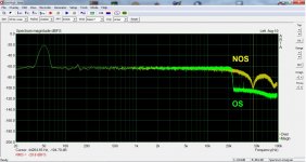
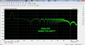
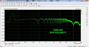
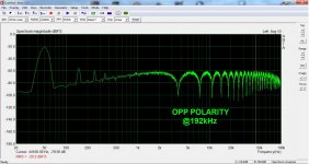
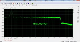
I focused on some better measurements. The first is the original NOS and OS signals. The second is the output of the diff amp. It is now clear to me that this is a comb filtering effect. How did I miss that? It means that the two signals are identical but slightly out of phase. The impulse response test was not valid. How on earth does all this come out as a clean measurable -last pic- and audible signal is a miracle. Apparently, NOS finds its opposite polarity in the time domain and cancels out letting the OS that arrives a bit later... or sooner(?) If anything else, the analog stage is up to the task! It just needs aligned inputs.
So, back to the starting point! It seems the delay to be 55/Fs. Should the NOS signal be delayed to align with OS? DDAC has already shift registers to delay data for 7 cycles to convert I2S to right justified and uses BCK instead of MCLK to compensate for the digital filter bypass. Is it possible to ever have NOS and OS aligned under these conditions? Could I simply add shift registers somewhere? I could use your help here since I'm completely clueless about all this...
Attachments
Oops! Thanks for pointing that. Anyway, I realize that I should not add anything in front of DDDAC as it might mess with the clock. And I guess I can't just speed up the OS DAC. Perhaps if I could delay it more to reach at 180 deg wrt to NOS and do that in the analog world.
Not exactly on topic update...The original concept was naive technically and theoretically. Even if it had worked it wouldn't had answered my question. Which was if interpolation eliminates the ultrasonic images or if filtering the images results to interpolation and if one can happen without the other. I now know that one cannot separate time domain from frequency domain. Then this thread came up https://www.diyaudio.com/community/...makes-nos-sound-different.371931/post-6643742 to shed light on the eternal question. My DAC was rebuilt keeping NOS and oversampling outputs independent and switchable. This was a revelation since it was the first time I could compare NOS to oversampling equally treated and side by side. Even so, it took some effort to track down the difference. It's not what we remember having listened DACs here and there... Oversampling sounds very nice, transparent and accurate. You will only know it's lifeless when you switch to NOS. Same soundstage, same volume but a whole big difference in dynamics. The instruments are vibrating in a natural way. It is more easily perceived at the lower frequencies. It is there at higher frequencies too but it feels like something is missing. At the very high frequencies this is not a big problem. True to life, vibrating cymbals are more preferred than sibilant. But in the low treble it leaves you wish for more. It's like it has the energy but not enough info. In the above mentioned thread it was made clear that neither the ultrasonic images nor the sinx/x drop in the audio range play any significant role in all this. So, if it all was about the interpolation method, I thought to try a completely passive LC filter, namely @abraxalito 's "Clelibidache" 9th order. And I'm very happy I did that. It steals just a bit from the dynamics but restores all the detail. NOS with passive I/V and LC reconstruction filter is my new preference.
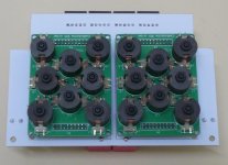
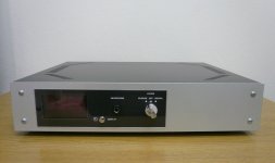
I'm reposting here pictures from the gallery for completeness. Three filter options: digital for oversampling, off for NOS and passive for NOS with the LC filter.
I'm reposting here pictures from the gallery for completeness. Three filter options: digital for oversampling, off for NOS and passive for NOS with the LC filter.
Attachments
Hi George!Again, hats off to you for the implementation!
You also have the ability to explain things nicely.
I would love to see the architecture of this beauty as a block diagram.
George
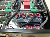
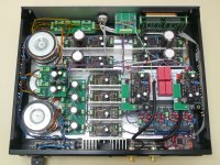
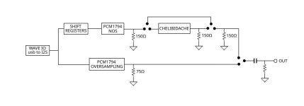
Here is a quick schematic. As said, it is based on DDDAC, it started with original boards but I had to move to custom PCBs to save space. So, there is a small blue board with the shift registers sitting on the red WAVE IO module directly on pin headers. Then the black board holds a DDDAC clone -let's call it NOS from now on- together with another pair of PCM1794 working on the same operation points but configured in oversampling mode. Independent outputs for all chips with passive I/V. The Celipidache filter needs 150 ohm load but I wanted a lower I/V resistor for the PCM1794 so I split the current with another 150 ohm in front of the filter. It works like one 75 ohm, I see no difference in THD+N, DC offset and rms output measurements between oversampling, raw NOS and filtered NOS. I do see the expected difference in frequency response and oscilloscope waveforms. Relays on the white board select the output options. The rest is Salas circuitry. I wanted to bring a pair of UltraBib right on the DAC board and I had to use 12V preregulators that supply the relays as well. Since the stupid hybrid thing was discarded, I was left with a full dual symmetric UltraBib that it was more painful to remove so I thought to use it for a TPA6120 headphone amp that I had from an old soundcard. Pretty much this is all. Let me know if there is anything else you want me to explain.
Attachments
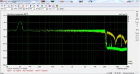
Hi Doede!Hi Magicbus, just read this post…. just saying, the DDDAC in „NOS“ mode, in fact non digital filtering, has no fall of at the end of the spectrum 20kHz, like TDA1543 DAC for example. So bit confused on your remarks in post nr 1 ?
If I understand correctly, you are saying that the DDDAC doesn't show the typical NOS -3dB drop at 20kHz? I'm not an expert in all this and my measurement equipment is primitive, but already from the days I was using your boards I had measured the attached which is the difference between NOS and oversampling at 44,1kHz. Of course, it's not unlikely that I had messed it up somewhere...
Attachments
- Home
- Source & Line
- Digital Line Level
- NOS, Oversampling... and now Hybrid(?)