
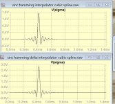
I will try to interpolate the midpoints of the derivatives, by this the sinc ringingings get subjected to delta sigma filter. After all I am interpolating the cubic spline of the derivatives and no more that of the data.
I will also use the heterodyne to add instead of filtering the 68k-88khz images.
There is still lot to do.
I will also use the heterodyne to add instead of filtering the 68k-88khz images.
There is still lot to do.
I tried a 36point Blackman Harris window while not using the outer 4 points because they were practically zero, so filter length stayed still the same as before.
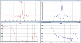
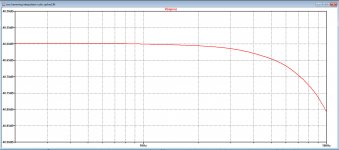
Below, at the left Blackman Harris in Red t and the Hamming with 0,45% gain at the right in Blue.
FR is now a bit smoother around 20Khz, but stopband is much deeper that the Hamming window with 0,45% gain.
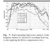
Suppression at 24.1Khz is a bit less, but to be realistic, at this frequency the spectral content of music is quite a bit lower, see second image.
Hans
.
Below, at the left Blackman Harris in Red t and the Hamming with 0,45% gain at the right in Blue.
FR is now a bit smoother around 20Khz, but stopband is much deeper that the Hamming window with 0,45% gain.
Suppression at 24.1Khz is a bit less, but to be realistic, at this frequency the spectral content of music is quite a bit lower, see second image.
Hans
.
Attachments


An advantage that very short filters, very long filters and minimum-phase filters have in common is their reduction of the passband-ripple-related pre-echo. That's something else than the ultrasonic pre-ringing. Using very short filters reduces the time between the pre-echo and the main signal, very long filters reduce the level of the pre-echo and minimum-phase filters simply haven't got a pre-echo. See the attachment for an explanation about the relation between passband ripple and pre-echo.
Attachments
Is this the formula you used?
View attachment 927313
That's the one, although my formula had N instead of N-1.
Here are the values that I used:
0.63382, -0.20393, 0.11397, -0.07312, 0.04922, -0.03352, 0.02267, -0.01505
0.00970, -0.00603, 0.00359, -0,00202, 0.00106, -0.00051, 0.00022
And I discarded the last three -0.00008, 0.00002, -0.00000.
Hans
An advantage that very short filters, very long filters and minimum-phase filters have in common is their reduction of the passband-ripple-related pre-echo. That's something else than the ultrasonic pre-ringing. Using very short filters reduces the time between the pre-echo and the main signal, very long filters reduce the level of the pre-echo and minimum-phase filters simply haven't got a pre-echo. See the attachment for an explanation about the relation between passband ripple and pre-echo.
Marcel,
Interesting paper, but it produces more questions than answers.
1. A filter with an impulse response consisting of a pre-echo, a main response and a post-echo produces exactly this kind of equidistant ripple response.
That is, when the echoes occur a time T before and after the main signal and have a magnitude α.
This pre- and post-echo definition here is here confusing.
At some places it looks as if echo is referring to pre- and post-ringing. At other places it almost seems as if he is referring with this echo to the ripple in the pass band.
And what exactly is the parameter α, is this the magnitude of the ripple in the passband or from the pre- and post-ringing, or is it even the deviation from the zero crossing points in the impulse response ?
If from post- and pre-ringing, how does one define the magnitude α of a decaying signal ?
2. Cascade the filter under test with an ideal continuous-time low-pass filter with cut-off frequency fmax.
As we are interested in what happens below fmax, this doesn't affect the part of interest.
When the passband is perfectly flat, the impulse response of the combined filter now has a sin(2πfmaxt)/(2πfmaxt) shape.
An ideal continuous-time low-pass filter with cut-off frequency fmax, already has a sin(2πfmaxt)/(2πfmaxt) shape.
So why should the cascade of filters now also have this shape?
3. Sample the impulse response of the combined filter with a sample rate of 2 fmax and ensure that the samples fall on the zero crossings of the sin(2πfmaxt)/(2πfmaxt) function.
Ideally, this produces only one nonzero sample, the one related to the main response.
Any other peaks or sin(x)/x shaped ripples are due to the imperfect passband response of the filter under test.
In Hayk’s application all samples at 2fmax are zero except one, so no ripple in the passband ?
4. Step 1 can be done mathematically by calculating the convolution of the impulse responses of the filter under test and the ideal filter. .
The convolution of the step response of both cascaded filters boils down to cut off everything from the filter under test above fmax in the frequency domain
When doing an IFFT of the cascaded FR, we get a somewhat modified impulse response.
By looking at distances 1/2fmax, the deviations from zero are now supposed to have a direct relation to the ripple in the passband, is that what is meant here ?
If so, a rather confusing route IMO was taken to get to this point.
Hans
Last edited:
Marcel,
Interesting paper, but it produces more questions than answers.
1. A filter with an impulse response consisting of a pre-echo, a main response and a post-echo produces exactly this kind of equidistant ripple response.
That is, when the echoes occur a time T before and after the main signal and have a magnitude α.
This pre- and post-echo definition here is here confusing.
At some places it looks as if echo is referring to pre- and post-ringing. At other places it almost seems as if he is referring with this echo to the ripple in the pass band.
And what exactly is the parameter α, is this the magnitude of the ripple in the passband or from the pre- and post-ringing, or is it even the deviation from the zero crossing points in the impulse response ?
If from post- and pre-ringing, how does one define the magnitude α of a decaying signal ?
This refers to a hypothetical filter with an impulse response consisting of only three peaks, one with magnitude alpha, one with magnitude 1 and one with magnitude alpha, so it has no ringing. This hypothetical filter is only used to model the passband ripple.
2. Cascade the filter under test with an ideal continuous-time low-pass filter with cut-off frequency fmax.
As we are interested in what happens below fmax, this doesn't affect the part of interest.
When the passband is perfectly flat, the impulse response of the combined filter now has a sin(2πfmaxt)/(2πfmaxt) shape.
An ideal continuous-time low-pass filter with cut-off frequency fmax, already has a sin(2πfmaxt)/(2πfmaxt) shape.
So why should the cascade of filters now also have this shape?
Because the cascade is still an ideal low-pass filter, and an ideal low-pass filter has a sinc impulse response.
3. Sample the impulse response of the combined filter with a sample rate of 2 fmax and ensure that the samples fall on the zero crossings of the sin(2πfmaxt)/(2πfmaxt) function.
Ideally, this produces only one nonzero sample, the one related to the main response.
Any other peaks or sin(x)/x shaped ripples are due to the imperfect passband response of the filter under test.
In Hayk’s application all samples at 2fmax are zero except one, so no ripple in the passband ?
That would be the consequence, yes. Do you see a passband ripple or only monotonic roll-off? Any signs of echoes?
4. Step 1 can be done mathematically by calculating the convolution of the impulse responses of the filter under test and the ideal filter. .
The convolution of the step response of both cascaded filters boils down to cut off everything from the filter under test above fmax in the frequency domain
When doing an IFFT of the cascaded FR, we get a somewhat modified impulse response.
By looking at distances 1/2fmax, the deviations from zero are now supposed to have a direct relation to the ripple in the passband, is that what is meant here ?
If so, a rather confusing route IMO was taken to get to this point.
Hans
Yes. I'm trying to find a relation between the pre- and post-echoes and the passband ripple without needing to assume that the filter is a cascade of a hypothetical low-pass with perfectly flat passband and a hypothetical filter that causes the passband ripple, but has perfectly equal distances between the ripples.

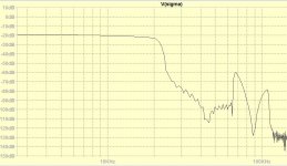
While you are considering my interpolator as filter, I am trying to filter out nothing. For that, I tried the heterodyne to decrease the images 68k-88khz.
I succeeded for 20khz,

but for global it is not so effective, with and without.

To clean up the output from spikes, I added S/H on the derivatives outputs.
I succeeded for 20khz,
but for global it is not so effective, with and without.
To clean up the output from spikes, I added S/H on the derivatives outputs.
Attachments
Last edited:


- Status
- This old topic is closed. If you want to reopen this topic, contact a moderator using the "Report Post" button.
- Home
- Source & Line
- Digital Line Level
- Analog Delta-Sigma interpolation DAC