I recalculted your filter coefficients, because 3% or even 7.3% sounds odd.
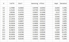
Here are my more accurate results:
0.63502, -0.20743, 0.11948, -0.08020, 0.05732, -004208, 0.03113, -0,02292
0.01664, -0.01182, 0.00817, -0.00548, 0.00361, -0.00242, 0,00181.
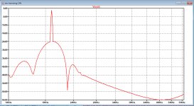
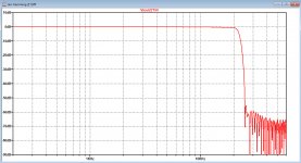
With these coefficients spectrum with your 20Khz sine wave input is in the first picture below, and the FFT of the impulse response is the second image.
Both are much smoother as before.
Hans
.
Here are my more accurate results:
0.63502, -0.20743, 0.11948, -0.08020, 0.05732, -004208, 0.03113, -0,02292
0.01664, -0.01182, 0.00817, -0.00548, 0.00361, -0.00242, 0,00181.
With these coefficients spectrum with your 20Khz sine wave input is in the first picture below, and the FFT of the impulse response is the second image.
Both are much smoother as before.
Hans
.
Attachments
How did you calculate? considering the first coefficient. The sinc is 1/(.5*pi)=0.6366 to multiply by the Hamming window (0.54+0.46(cos(2*pi/30))= 0.9899 I get 0.63022. How you find 0.63502?
I see, you consider the Window also with half factor, I thought the window acts upon the samples.
I see, you consider the Window also with half factor, I thought the window acts upon the samples.
Last edited:


How did you calculate? considering the first coefficient. The sinc is 1/(.5*pi)=0.6366 to multiply by the Hamming window (0.54+0.46(cos(2*pi/30))= 0.9899 I get 0.63022. How you find 0.63502?
I see, you consider the Window also with half factor, I thought the window acts upon the samples.
Here they are.
Hans
.
Attachments
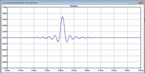
I feel shameful to give you such troubles. The Hamming window I made it double bell on one each 15th and 16th sample. It works marvelous. I added now the cubic interpolator, I don't know yet, why I have spikes after the integrator, this what I get with pulse response.


Attachments
A funny intermezzo.
Look at this T+A DAC test in Stereophile with four different filters.
T+A Elektroakustik DAC 8 DSD D/A processor | Stereophile.com
Filter 3, a combination of Bezier curve interpolation and IIR filter was regarded to produce the best sound.
But look at the huge first mirror from a 19Khz tone at 25Khz.
So how important can it be to suppress this image?
No mentioning at all of harsh sound.
I’m lost with all those opinions contradicting each other.
Hans
The T+A DAC 8 DSD is one described by ClaudeG in the ES9038Q2M thread. IIIRC it is not considered the best for PCM, but perhaps the best or one of the very best for DSD (the Stereophile article briefly talks about it, but they skipped trying the dac with high sample rate DSD).
Last edited:
I feel shameful to give you such troubles. The Hamming window I made it double bell on one each 15th and 16th sample. It works marvelous. I added now the cubic interpolator, I don't know yet, why I have spikes after the integrator, this what I get with pulse response.
View attachment 925717
View attachment 925718
You can improive things quite a bit by lining up V5 with the other signals.
Set fall time to 1nsec and delay to 2u061.
Also from the delay lines generating S1 to S-2 you can attach small 30pF caps to catch the spikes.
Succes,
Hans
.
Attachments


So instead of having three filters working in parallel instead of the single Sinc Hamming filter you have now, you want to put a complete copy in series with what you have, but now at twice the frequency ?
That will then remove the second mirror but also introduce unwanted pre ringing at twice the frequency.
To interpolate more points then you have now, it seems better to use two or three Sinc Hamming polyphase filters in parallel working at Fs to get two or three interpolated points between the original points.
In that case, the length and frequency of the pre and post ringing will stay the same
Hans
For your first proposition, the new ringing at double frequency is what I wish to filter out by a notch. A quick sim showed that the precedent ringing remains as is, so not a solution.
May be I can interpolate the sinc by linear phase filter method to have it without pre resonance.
May be I can interpolate the sinc by linear phase filter method to have it without pre resonance.
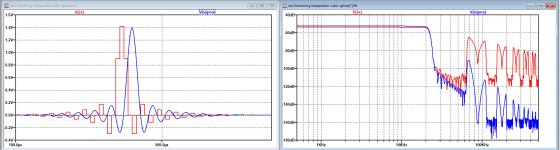
Nevertheless, I optimised your last .asc for exactly 44.1Khz and plotted the filter before and after your smoothing filter.
Results are looking very good, see below.
Mirror at 88,2Khz is suppressed by almost 40dB.
Hans
.
Results are looking very good, see below.
Mirror at 88,2Khz is suppressed by almost 40dB.
Hans
.
Attachments
Last edited:

I find the stm32h750 DSP the best suited for audio. Not only it has particular PLL for I2S, It has 3 I2S channels plus four SAI can be programmed to be any audio formats. A board with 8MB flash prom, USB, MicroSD, cost only 12$ ship.incl. +2$ for USB stick downloader.
STM32H750VBT6 STM32H743VIT6 STM32H7 Development Board STM32 System Board M7 Core Board TFT Interface with USB Cable|Instrument Parts & Accessories| - AliExpress
STM32H750VBT6 STM32H743VIT6 STM32H7 Development Board STM32 System Board M7 Core Board TFT Interface with USB Cable|Instrument Parts & Accessories| - AliExpress
Measuring in continuous mode gives different image ratio than the impulse.
View attachment 926011
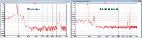
I think your image is not as good as it could, that's why I include your optimised .asc file.
Two images below with a 20Khz 1.414V sinus wave input , the first from 0 to 5msec, giving this funny bulge below 20Khz, the second one from 1msec to 6msec, giving a better view on things.
Hans
.
Attachments
Looks very attractive.I find the stm32h750 DSP the best suited for audio. Not only it has particular PLL for I2S, It has 3 I2S channels plus four SAI can be programmed to be any audio formats. A board with 8MB flash prom, USB, MicroSD, cost only 12$ ship.incl. +2$ for USB stick downloader.
What about software, and in what programming language ?
Hans
So instead of having three filters working in parallel instead of the single Sinc Hamming filter you have now, you want to put a complete copy in series with what you have, but now at twice the frequency ?
That will then remove the second mirror but also introduce unwanted pre ringing at twice the frequency.
To interpolate more points then you have now, it seems better to use two or three Sinc Hamming polyphase filters in parallel working at Fs to get two or three interpolated points between the original points.
In that case, the length and frequency of the pre and post ringing will stay the same
Hans
I expect that the pre- and post-ringing will be determined by the filter with the narrowest bandwidth, so it will stay around 22050 Hz no matter which of the two solutions is chosen. At least with ideal filters, the two solutions would be completely equivalent.
Has a free download/online C/C++ compiler common to all family. The manual of the DSP is 3000 pages. I think the USB is used to read/write rather than to communicate. To have low jitter better to use a serious input combo adapter.Looks very attractive.
What about software, and in what programming language ?
Hans
Last edited:
- Status
- This old topic is closed. If you want to reopen this topic, contact a moderator using the "Report Post" button.
- Home
- Source & Line
- Digital Line Level
- Analog Delta-Sigma interpolation DAC