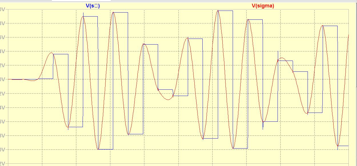
This the integrator output with the ramp, linear interpolation+additive. The magic formula of the additive is
1/2[(-3s-₁+9s₀-9s₁+3s₂)P² +(4s-₁-10s₀+8s₁-2s₂)P+(-s-₁+2s₀+s₁)]
P is a ramp =0v at the start of the sample =1v at the end. P² is the square of P.
Attachments
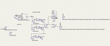
I replaced the sampled data into its delta's to avoid dealing with low frequencies to be exactly subtracted before being additive. The result on simulator is identical.
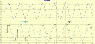
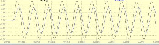
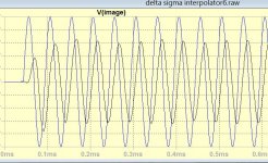
This is the reconstructed 20khz.
Is there any means to reconstruct the sampling beat?
How this phenomena is treated in DACs?
This is the reconstructed 20khz.
Is there any means to reconstruct the sampling beat?
How this phenomena is treated in DACs?
Attachments

Last edited:
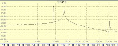
You see the sum of 20 kHz and its image at 24.1 kHz, so you could remove it with a steep filter that has 20 kHz in its passband and 24.1 kHz in its stopband. If you also want to remove images for signals between 20 kHz and the Nyquist frequency, 22.05 kHz already has to be in the stopband.
Up to 10khz, The sigma output is very good.

I will keep this signal as the essential cut 2nd order low pass to be complimented by a pass band 10k-20khz, a two way DAC, so that the essential of the music remains untouched.
Once I master the high frequency zone, afterwards I see if I can reunite them in one way.
I will keep this signal as the essential cut 2nd order low pass to be complimented by a pass band 10k-20khz, a two way DAC, so that the essential of the music remains untouched.
Once I master the high frequency zone, afterwards I see if I can reunite them in one way.
Last edited:
I tried Abraxalito's current driven filter he was using in Ling DAC that I simulated.
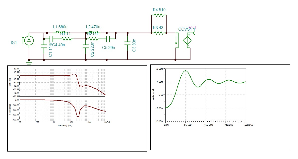
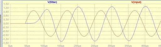
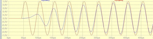
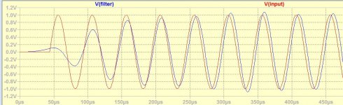
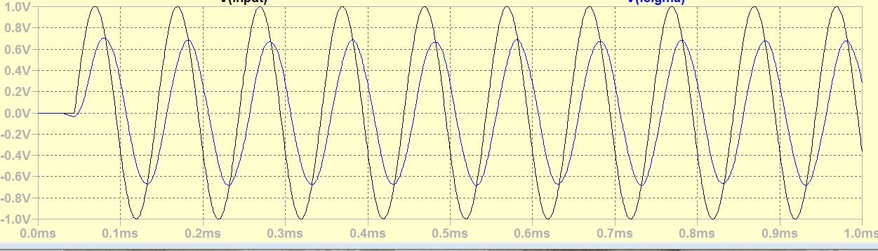
First I fed with the s₀, these are the results with 10khz and 20khz.
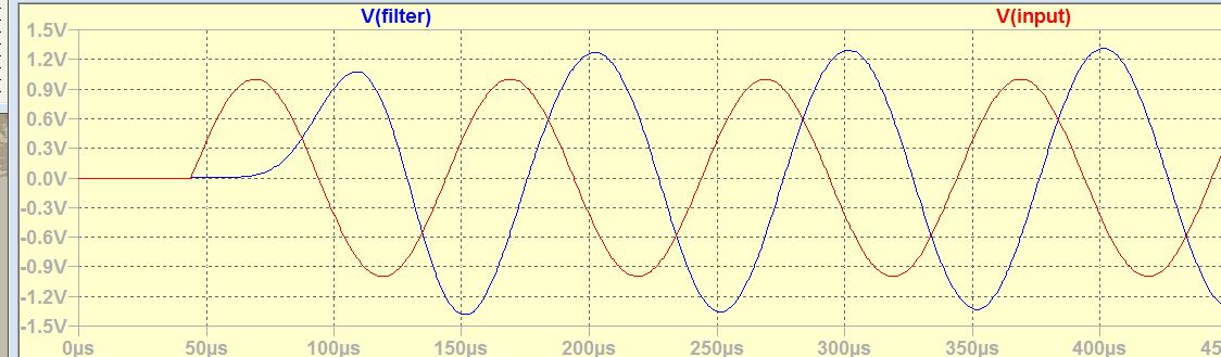
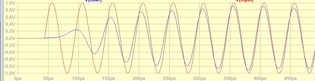
despite the filter has some resonant gain at 20khz, it is not sufficient to correct the sinc function. So I fed with the most early delta d₁, this is the result.
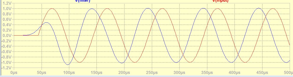
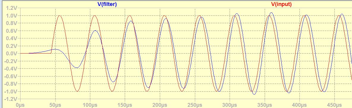
The 20khz phase if well adjusted the 10khz one is to submitted to extra high pass filter.
Comparing the 20khz standard signal with the delta one, the amplitude linearity the envelop speed no doubt the delta is the winner. I didn't yet touch the filter.
First I fed with the s₀, these are the results with 10khz and 20khz.
despite the filter has some resonant gain at 20khz, it is not sufficient to correct the sinc function. So I fed with the most early delta d₁, this is the result.
The 20khz phase if well adjusted the 10khz one is to submitted to extra high pass filter.
Comparing the 20khz standard signal with the delta one, the amplitude linearity the envelop speed no doubt the delta is the winner. I didn't yet touch the filter.
Attachments
Last edited:
I would like to try out other image filters if someone can suggest me, particularly from 1st generation high quality cd players. I found a patent shown bellow of image filter, which looks like, as me, the designer didn't understood the main task of this filter. By googling, the only circuits I see are of Abraxalito. I tried his 7th order filter, a disaster, so the only valid one I have is his old version 5th order, the new version that
he does provide, PCB or wired/tested , the circuit is not available.
he does provide, PCB or wired/tested , the circuit is not available.
Attachments
Last edited:
I don't believe filtering is the solution. I will never get the same delay at 10khz as 20khz. With 5th order the best I could get is -90° at 20khz and -270° at 20khz, 80° phase shift difference is unacceptable.
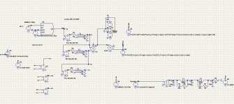
I took back my pilgrim's baton and try out to unmodulate. I multiplied the sigma output with the Nyquist carrier to AM demodulate, I shift the image to low frequencies, once filtered I got the beat wave.
I get a delay due to the filter, but I have sufficient data to be able to unmodulate.
I took back my pilgrim's baton and try out to unmodulate. I multiplied the sigma output with the Nyquist carrier to AM demodulate, I shift the image to low frequencies, once filtered I got the beat wave.
I get a delay due to the filter, but I have sufficient data to be able to unmodulate.
Attachments
So you have an image at 24100 Hz that you frequency convert to 2050 Hz, precisely where your ears are most sensitive?
If you want phase linearity and suppression of images, a brute-force solution would be a very long FIRDAC with sinc-shaped weighting: take a few hundred DACs driven from a delay line and take a weighted sum of their outputs. Or just use an oversampling digital filter.
If you want phase linearity and suppression of images, a brute-force solution would be a very long FIRDAC with sinc-shaped weighting: take a few hundred DACs driven from a delay line and take a weighted sum of their outputs. Or just use an oversampling digital filter.
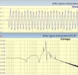
The image reduced to low frequency maybe can serve me to undemodulate by multiplication, not sure. What is astonishing, if I use sinusoidal carrier 22.7k multiplying directly the raw DAC output I get the following spectrum.
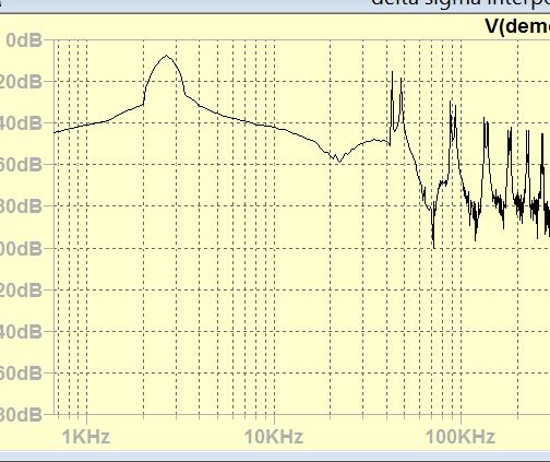
As I will use only 10k min , I don't need a difficult filter.
About digital filtering, it can be trusted the high frequency 10k to 20k, to oversampled DAC as TDA1305T, but then I need an armada of shift registers mc14517 to compensate the DAC delay.
As I will use only 10k min , I don't need a difficult filter.
About digital filtering, it can be trusted the high frequency 10k to 20k, to oversampled DAC as TDA1305T, but then I need an armada of shift registers mc14517 to compensate the DAC delay.
Attachments
I have another idea simmering in my head, instead of eliminating the image by filtering why not bring it to reality by bandpass filter 24khz to 34khz and subtract from the signal, by this, the attenuated but not eliminated main signal after the bandpass will slightly alter the signal level for worst . What do you think?
") Just switch the cables if you are sensitive to absolute phase :-D
Just switch the cables if you are sensitive to absolute phase :-DI have another idea simmering in my head, instead of eliminating the image by filtering why not bring it to reality by bandpass filter 24khz to 34khz and subtract from the signal, by this, the attenuated but not eliminated main signal after the bandpass will slightly alter the signal level for worst . What do you think?
I think you should write out the transfer function of the bandpass filter you have in mind, say Hbp(s) = some polynomial in s divided by some other polynomial in s, then calculate 1 - Hbp(s) and see what that does to signals in the 0 to 20 kHz range. Effectively you will be making a bandstop filter.
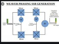
I am trying out the weaver SSB modulator. I need a pair of reduced image waves 90 phase shift trough the whole band 2khz(20khz) to 12khz(10khz).
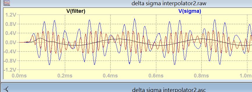
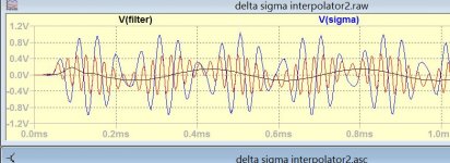
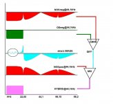
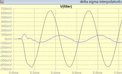
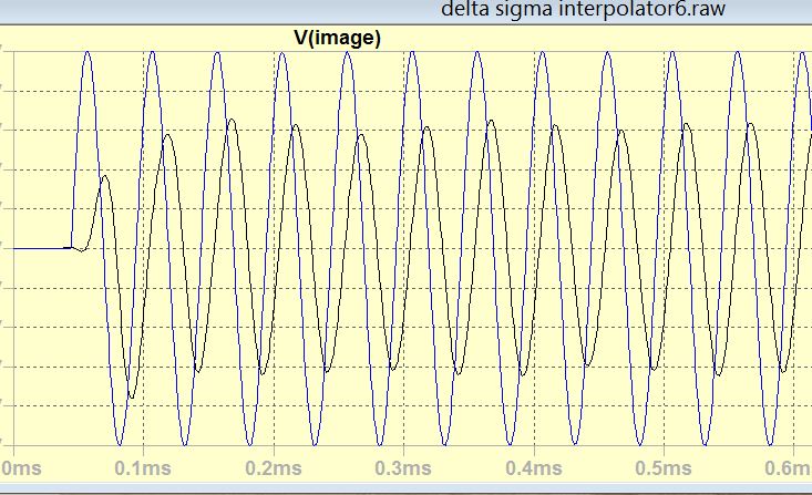
By multiplying the DAC output by two Nyquist sin waves in 90 phase, I get the reduced images of following for 5, 10, 15, 20khz .
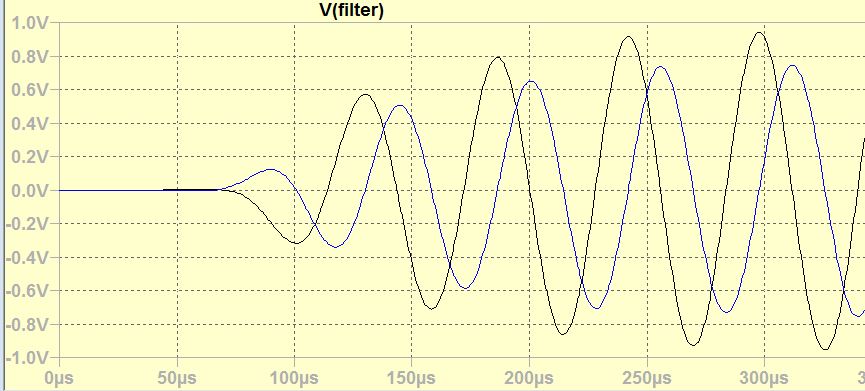
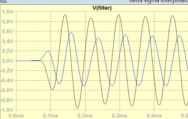
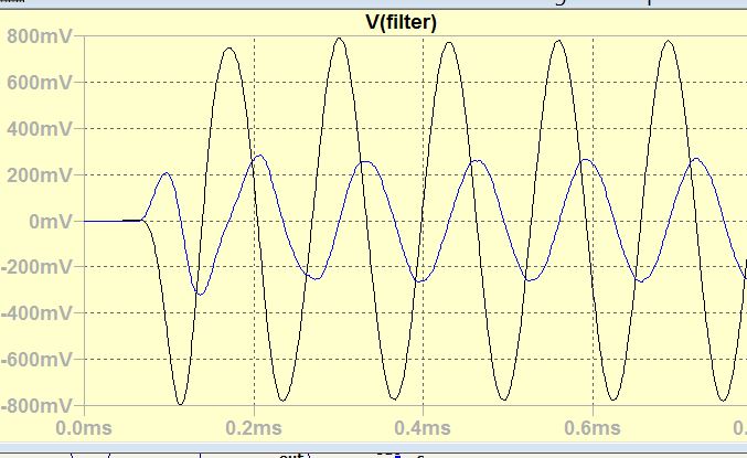
The black curves are the products of 0°Nyquist and the blue 90°
The mission is to have the blue and the black curves remain equal.
What I am wondering, why the image of lower frequencies are higher then higher ones? Shouldn't it be the contrary?
By multiplying the DAC output by two Nyquist sin waves in 90 phase, I get the reduced images of following for 5, 10, 15, 20khz .
The black curves are the products of 0°Nyquist and the blue 90°
The mission is to have the blue and the black curves remain equal.
What I am wondering, why the image of lower frequencies are higher then higher ones? Shouldn't it be the contrary?
Attachments
Last edited:
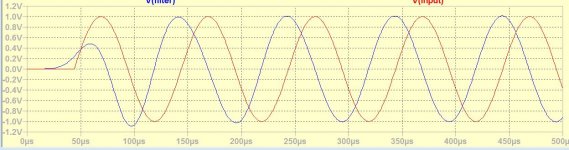
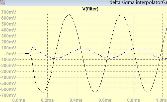
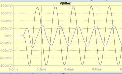
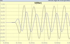
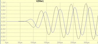
This is what the NOS + interpolator gives at 10khz after 1st order low pass 10khz applied.
On this need to be added 10k to 20khz with high pass, this is best 20khz I get with Weaver modulator.
It is still long way to go to get such uniform response 10k to 20khz.
I will see what can I do with Hartley modulator.
On this need to be added 10k to 20khz with high pass, this is best 20khz I get with Weaver modulator.
It is still long way to go to get such uniform response 10k to 20khz.
I will see what can I do with Hartley modulator.
Attachments
Last edited:
- Status
- This old topic is closed. If you want to reopen this topic, contact a moderator using the "Report Post" button.
- Home
- Source & Line
- Digital Line Level
- Analog Delta-Sigma interpolation DAC