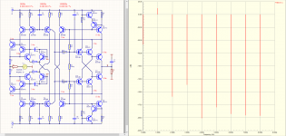
I've had some time over the past few weeks to spend time listening to this stage on an AD1862 DAC. It really is a lovely performer and well worth building. The bass is quite something - I don't think any other piece of kit I have gives quite such low and tight bass. It just sounds very "right", not clinical but with loads of detail. Very easy to listen to for very long periods. It is also very practical because it can be built on a very small footprint, is low current, doesn't need much heatsinking, low parts count, no caps other than Civ. But I know that doesn't really matter so much, its all about the sound quality. In short, I have been testing out a good number of output stages, and this one is staying in the final 2 that I will build.
Thank you EUVL for making the design of this public.
Thank you EUVL for making the design of this public.
Low current consumption is one point that stands out, compared to say the SEN IV.
It also uses all active parts with no unobtaniums, which makes life easier.
Also it has a built-in emitter folllower output stage with low output impedance.
These are the points that speak for the CM circuit.
So glad you like the sonics as well.")
Patrick
It also uses all active parts with no unobtaniums, which makes life easier.
Also it has a built-in emitter folllower output stage with low output impedance.
These are the points that speak for the CM circuit.
So glad you like the sonics as well.
Patrick
very encouraging
would you please post few pics with your build
which bjt are you using
would you please post few pics with your build
which bjt are you using
I've had some time over the past few weeks to spend time listening to this stage on an AD1862 DAC. It really is a lovely performer and well worth building. The bass is quite something - I don't think any other piece of kit I have gives quite such low and tight bass. It just sounds very "right", not clinical but with loads of detail. Very easy to listen to for very long periods. It is also very practical because it can be built on a very small footprint, is low current, doesn't need much heatsinking, low parts count, no caps other than Civ. But I know that doesn't really matter so much, its all about the sound quality. In short, I have been testing out a good number of output stages, and this one is staying in the final 2 that I will build.
Thank you EUVL for making the design of this public.
Please kindly start a new thread at the Group Buy Section to see if there is sufficient interest.
This thread should be left for technical discussion only.
We define one set as 5 PCBs.
There are left / right versions, of which 2 pairs will be supplied.
There is an additional "neutral" version which is meant for you to test build first.
I guess you don't want to use up your best matched devices for test build.
Many thanks for your interest,
Patrick
> Naturally, this is done and live results are not different.
Then many congratulations.
Why not open a separate thread for this outstanding design of yours and show us all how to do -150dB without negative feedback ?
I am certain there will be a lot of resonance from this forum.
Cheers,
Patrick
Then many congratulations.
Why not open a separate thread for this outstanding design of yours and show us all how to do -150dB without negative feedback ?
I am certain there will be a lot of resonance from this forum.
Cheers,
Patrick
Nothing exclusively in the scheme.
These things are known at least 30-40 years.
The problem is that no one understands from the schemes, just a copy without being understood how they work.
https://www.diyaudio.com/forums/digital-line-level/373375-discrete-iv-ifnverter.html#post6685644
These things are known at least 30-40 years.
The problem is that no one understands from the schemes, just a copy without being understood how they work.
https://www.diyaudio.com/forums/digital-line-level/373375-discrete-iv-ifnverter.html#post6685644
It will be fun to try this as an alternative output stage of the Pedja DAC with its AD844; thanks for the GB.
Can you please tell whether this i-v stage can also be used for an ES9038q2m dac with a differential output? For instance, would two per channel be required, with a mutual connection?
Can you please tell whether this i-v stage can also be used for an ES9038q2m dac with a differential output? For instance, would two per channel be required, with a mutual connection?
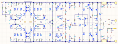
This is meant for +/-2mA max signal current per module.
Limitation is heat dissipation of the SMD devices.
So for higher signal current with a DC bias (e.g. PCM1794), you will need :
1) multiple modules in parallel per single ended output (PCB is designed for that);
2) a low-noise constant current source for DC bias.
It was designed for the likes of AD1862, PCM1704, etc in mind.
And not for high output current DACs, e.g. AK4499.
BTW a single AD844 can handle much less signal current (in Class A) due to its low bias.
Patrick
- Home
- Source & Line
- Digital Line Level
- A Simple Discrete Current-Mirror IV Converter, à la AD844