Hello,
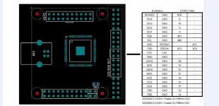
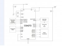
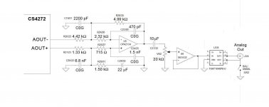
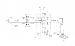
It's about an audio codec ADC/DAC CS4272 https://statics.cirrus.com/pubs/proDatasheet/CS4272_F1.pdf I'm trying to put it to work with this USB to I2S module XMOS Multichannel high-quality USB to/from I2S/DSD SPDIF PCB - DIYINHK Schematics are attached, as well as the DIYINHK module requirements. Connections seem quite straightforward. I'm assuming that BCK is the same as SCLK, correct?
The DIYINHK module gets recognized by the PC and the drivers are loaded. But I don't get any sign from CS4272. Even Vref and Vcom stay at 0V. Vcc and Vdd are OK. To my understanding this means power down mode, doesn't it? I tried two chips I had available and both do the same thing. There is some info on CS4272 datasheet page #35 about ADO/CS (pin #13) but my lack of knowledge doesn't help me with this... In my case (copied design) ADO/CS is attached to ground. Do you think this could be the reason?
I realize that remote debugging is too much to ask so, I would appreciate if you could at least verify Cs4272 and DIYINHK module campatibility.
Attachments
Additional info, some measurements with my DMM set for DC:
RST, SDA, SCL=3,3V
LRCK, BCK=1,5V
MCLK=1,6V
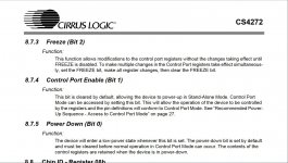
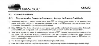
Attached a few extracts from the datasheet possibly related with my problem. In the last one : "The power down bit is set by default and must be cleared before normal operation in Control Port Mode can occur."
Any ideas?
RST, SDA, SCL=3,3V
LRCK, BCK=1,5V
MCLK=1,6V
Attached a few extracts from the datasheet possibly related with my problem. In the last one : "The power down bit is set by default and must be cleared before normal operation in Control Port Mode can occur."
Any ideas?
Attachments
Last edited:
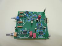
Thanks for reply! The dac board is my design according to the schematic of post #1. Essentially application notes implementation. I can provide a screenshot of the pcb design if needed. I want to make it work in full duplex -adc/dac. Basically, I understand that I2S is the main communication signal. I2C is supposed to do some other things. I surely can't tell what this should be and definitely I'm clueless about read/write code. I'm just using the usb module drivers. It would be nice if I2C could be omitted in my application but then how should I configure the hardware?
MagicBus,
Do you have an actual complete schematic, not just a simplified diagram? Where are the voltage regulators and what kind, etc.?
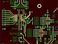
Also, it would probably be helpful to see the PCB layout.
By the way, still wondering if you have a scope?
Regarding I2C, its how you connect to the dac chip to control its register settings. That's important. Pretty easy to do with an Arduino or other MCU of your choice.
Do you have an actual complete schematic, not just a simplified diagram? Where are the voltage regulators and what kind, etc.?
Also, it would probably be helpful to see the PCB layout.
By the way, still wondering if you have a scope?
Regarding I2C, its how you connect to the dac chip to control its register settings. That's important. Pretty easy to do with an Arduino or other MCU of your choice.
Methinks, Sir Markw4, you doth have your work cut out for you.
Hi, nice to see you again. Maybe you won't be able to resist chiming in to help at some point, we'll see what happens.
Here is the psb layout. The board also holds input and output analog stages and those work fine. The voltage regulators -LT3042- are on another board also working.
Unfortunately, I haven't a scope...
Having had good luck with previous projects involving only dacs and I2S I thought it would be as easy to make this one work... But I2C is out of reach for me. I realize that it doesn't come complete with the drivers for the usb converter. As said in the first post, on no account I would like to put the forum into frustration for something that I could hardly follow. I keep the conclusion that the circuit does not work as is...
Attachments
Okay, thank you for posting those. Makes it much more clear.
How about we talk about I2C a bit? I have some Arduino code I can share that can read and write dac registers over I2C. I use it for random test changes to registers and also for preloading all the registers at once after power on. I haven't studied the data sheet for the dac chip you are using yet, but I'm sure I could explain what you would need to do. Its actually not hard and its something all diy dac builders should know how to do these days. Does that interest you?
Also, still not clear if you have a scope?
Okay, let's start at the beginning. Arduinos are a set of hobbyist microcontrollers mounted on a small PCB with a local voltage regulator and a USB interface. There are a few that can run on 3.3v, but most are 5v powered. They have lots of pins for interfacing to other hardware, and the pins are programmable in terms of their functionality. There are built in 10-bit (IIRC?) ADCs on pins that can also be used as digital inputs or outputs. It also has built in pullups that can be turned on or off for pins used for digital output. The programming language is a small set of more or less C++.
I happen to mostly use the "Trinket Pro 3.3v" variant. That particular Arduino needs an extra board attached to it in order to communicate over USB while it is running a program. The built-in USB interface can only be used for programming it. The add-on USB board for programming and or real time terminal communications is called an FTDI board. Something like these: Amazon.com: Adafruit Pro Trinket - 3V 12MHz: Computers & Accessories
Amazon.com: TinySine Micro USB FTDI Basic Breakout Module for Arduino 3.3V/5V: Computers & Accessories
There are two dedicated pins used for I2C bus that benefit from internal hardware timers to control bus timing. Besides the freeware Arduino compiler program, I also use a 3rd party I2C library: GitHub - felias-fogg/SoftI2CMaster: Software I2C Arduino library
With the compiler and the library it is easy to customize I2C code.
I2C bus wiki is at: I2C - What's That? - I2C Bus
Any questions so far?
Last edited:
I can understand hardware very well. Programming language and bits otoh are Greek to me  Many years ago, I was given a ready code and a PC program that I cannot recall but it was supposed to make it easy to load the code to the Mega(?) chip. I followed the instructions and build a board with regs and everything that was using a parallel port to connect to the PC. Complete failure... I never messed with these things again. That said, connecting boards and understand what they are expected to do is the easy part.
I read your post. So far so good. I'll read it again tomorrow. Now it's late night here. We need to take our time with this. I'll do my best the time not to be that long! Again many thanks!
Many years ago, I was given a ready code and a PC program that I cannot recall but it was supposed to make it easy to load the code to the Mega(?) chip. I followed the instructions and build a board with regs and everything that was using a parallel port to connect to the PC. Complete failure... I never messed with these things again. That said, connecting boards and understand what they are expected to do is the easy part. I read your post. So far so good. I'll read it again tomorrow. Now it's late night here. We need to take our time with this. I'll do my best the time not to be that long! Again many thanks!
New entry! The reason I kept it around I2C "software control" is simply because that was done on the circuits I shamelessly copied. If the punishment should be to learn I2C and arduino I won't complain and I'm seriously speaking!
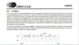
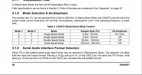
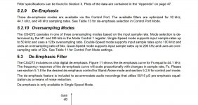
But if we could stay a little on the "stand-alone" please... According to datasheet, pin "ADO/CS" changes to "I2S/LJ" to select Serial Audio Interface with a pull up or pull down resistor -understood- and then SCL becomes M0 and SDA M1. The only info I can find about these is on page #26 - see extract attached. And then there is something about oversampling on page #31. Is it that I can set M0 and M1 for max speed so I could get all sampling rates from 44.1 to 192kHz at the lowest oversampling mode or do I have to adjust manually for the sampling rate each time?
If the punishment should be to learn I2C and arduino I won't complain and I'm seriously speaking! But if we could stay a little on the "stand-alone" please... According to datasheet, pin "ADO/CS" changes to "I2S/LJ" to select Serial Audio Interface with a pull up or pull down resistor -understood- and then SCL becomes M0 and SDA M1. The only info I can find about these is on page #26 - see extract attached. And then there is something about oversampling on page #31. Is it that I can set M0 and M1 for max speed so I could get all sampling rates from 44.1 to 192kHz at the lowest oversampling mode or do I have to adjust manually for the sampling rate each time?
Attachments
Traditionally, you put on the parachute before you jump.
Maybe when I stop laughing long enough to be able to write something
Hi, nice to see you again. Maybe you won't be able to resist chiming in to help at some point, we'll see what happens.
Maybe when I stop laughing long enough to be able to write something
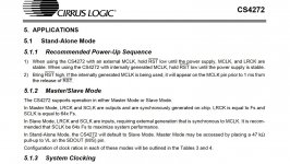
I just took a quick look at the data sheet. Looks like its is the power up sequence that determines stand alone mode verses software control mode.
Basically, if you want stand alone mode then you follow the power up sequence for it. In that case the pins function as shown on pages 7 and 8 of the data sheet. The remainder of the stand alone section of the data sheet describes how to use the pins to control what you can control that way.
For example, to play higher sample rates the there some pins that encode the sample rate for the dac to operate at. Those pins would have to get mapped to the F0-F3 pins of a USB board. In that case you need to know how the F0-F3 pins for your USB board work to know if any interface glue logic would be needed.
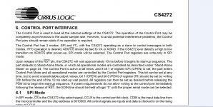
On the other hand, to operate in software control mode power up sequencing is critical to entry into software mode.
More I read, the more useful a scope looks.
So, pick a mode and study the data sheet section for what you want to do. Make some notes about when and how you will need to toggle the control pins, or set the register bits (as the case may be), and then start on a control side design to make it happen.
EDIT: Of course with the USB board you have right now, there will be no way to make the ADC work with it. Just so we all agree on that point.
Basically, if you want stand alone mode then you follow the power up sequence for it. In that case the pins function as shown on pages 7 and 8 of the data sheet. The remainder of the stand alone section of the data sheet describes how to use the pins to control what you can control that way.
For example, to play higher sample rates the there some pins that encode the sample rate for the dac to operate at. Those pins would have to get mapped to the F0-F3 pins of a USB board. In that case you need to know how the F0-F3 pins for your USB board work to know if any interface glue logic would be needed.
On the other hand, to operate in software control mode power up sequencing is critical to entry into software mode.
More I read, the more useful a scope looks.
So, pick a mode and study the data sheet section for what you want to do. Make some notes about when and how you will need to toggle the control pins, or set the register bits (as the case may be), and then start on a control side design to make it happen.
EDIT: Of course with the USB board you have right now, there will be no way to make the ADC work with it. Just so we all agree on that point.
Last edited:
Are you sure that what the USB board is sending to the dac is what the dac is configured to receive? e.g I2S 16/44, or whatever it happens to be. If unsure, you need to look at the signals with a scope to make sure they look right, and then maybe try some alternate settings, perhaps such as LJ.
Really, I think anyone who wants to build audio electronics, especially dacs, needs to have a scope and to learn how to use it. Otherwise, one can't check essential things. Any scope, a used analog scope would be better than no scope. For dac work, I would say a 100MHz 2-channel scope is minimal. They are cheap now too compared to the old days.
Really, I think anyone who wants to build audio electronics, especially dacs, needs to have a scope and to learn how to use it. Otherwise, one can't check essential things. Any scope, a used analog scope would be better than no scope. For dac work, I would say a 100MHz 2-channel scope is minimal. They are cheap now too compared to the old days.
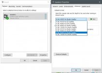
There is something you can check. If you are using Windows as the USB host for your USB board, you should check the sound settings in Windows Control panel. Please see the screenshot pic below. If you select the diyinhk sound device, then click on the properties button, it will open the properties window. Click on the advanced tab and see what the default sample rate is set to. If not set at 16/44, try changing it to that. Then hit Apply, then try sending audio to the USB board again.
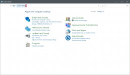
If you don't know how to get to the sound settings, take a look at the 2nd screenshot below. Type Control Panel in the search box on the task bar, select Windows control panel, then click on the right arrow button outlined in red in the pic. That should cause other options to appear at which point click on All Control Panel Items.
If you don't know how to get to the sound settings, take a look at the 2nd screenshot below. Type Control Panel in the search box on the task bar, select Windows control panel, then click on the right arrow button outlined in red in the pic. That should cause other options to appear at which point click on All Control Panel Items.
Attachments
Last edited:
I confirm that the usb board is working. I can check all settings in the Windows Control Panel. And when I touch the data input I get "signal" on ARTA FFT. Admittedly, quite primitive way to check functionality... Acquiring an oscilloscope is on my list to do. Unfortunately, they cannot be found that cheap in this part of the world.
Something that puzzles me: is there any chance I have reversed data in and out lines? I took it for granted that SDIN is data for the ADC and SDOUT for the dac.
Something that puzzles me: is there any chance I have reversed data in and out lines? I took it for granted that SDIN is data for the ADC and SDOUT for the dac.
- Status
- This old topic is closed. If you want to reopen this topic, contact a moderator using the "Report Post" button.
- Home
- Source & Line
- Digital Line Level
- CS4272 stuck in power down mode