Dear forum members
Anybody have experience with I2SoverUSB MK3 card and AD1865DAC? I tried to setup according to the user manual,
http://jlsounds.com/uploads/I2SoverUSB v.III.pdf
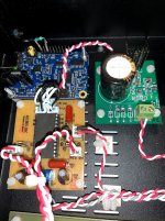
(J3 jumper closed, H1.1 connect H1.3 with 4.7k resistor), then connect the board to the DAC but no sound.
I checked the H3.9, H3.11, H3.13 H3.15 with my scope, I see the square signals, so the outputs are working, but maybe the data format not good...
What is MCLK_2/4 or MCLK_2/2 options?
Thanks
Laszlo
Anybody have experience with I2SoverUSB MK3 card and AD1865DAC? I tried to setup according to the user manual,
http://jlsounds.com/uploads/I2SoverUSB v.III.pdf
(J3 jumper closed, H1.1 connect H1.3 with 4.7k resistor), then connect the board to the DAC but no sound.
I checked the H3.9, H3.11, H3.13 H3.15 with my scope, I see the square signals, so the outputs are working, but maybe the data format not good...
What is MCLK_2/4 or MCLK_2/2 options?
Thanks
Laszlo
Attachments
Thanks,
yes, you can see at the first post there are a jumper on the J3 position, and the resistor between H1.1 and H1.3, according to the manual.
I just want to figure out why not working with my DAC. B1-B5 and B1-B6 is a difference between the manual, and the current version of the PCB.
yes, you can see at the first post there are a jumper on the J3 position, and the resistor between H1.1 and H1.3, according to the manual.
I just want to figure out why not working with my DAC. B1-B5 and B1-B6 is a difference between the manual, and the current version of the PCB.
...B1-B5 and B1-B6 is a difference between the manual, and the current version of the PCB.
True, but B6 appears to be for future expansion. If still concerned about it there is contact information on the JL Sounds website so you can ask them directly (email: info@jlsounds.com). If can take a few days for them to respond IME.
What kind of scope do you have, one with 4-channels? Maybe you can look at signals with it. Otherwise, you might have to compare two at a time, and or keep checking for other problems you may have overlooked with your project.
Now it's working.
I don't know what happened, I disconnected from my DAC, I removed the board from the enclosure to check with my scope again. I soldered the 4.7k resistor directly to the back of the PCB. Maybe the resistor was wrong, or the contact was wrong I don't know, it is working now.
Thanks
I don't know what happened, I disconnected from my DAC, I removed the board from the enclosure to check with my scope again. I soldered the 4.7k resistor directly to the back of the PCB. Maybe the resistor was wrong, or the contact was wrong I don't know, it is working now.
Thanks

What’s your opinion about the sound?
I also have a 1865 chip that i haven’t build yet..
BR // Daniel
Earlier I used Amanero with Ian’s I2StoPCM board. As Ian mentioned for the best result it’s need to add a FIFO recklock board. I didn’t have this FIFO board in my previous setup.
Maybe this is the reason why I hear the I2SoverUSB board a little more detailed. Or because it is newer, and the new things sounds better [emoji1]
As always they sounds best with an external supply setuped with care. If you can, uf-l wires between 2" and 4" max.
Whatever the FiFO, still things can be heard and yet the supply play an important role as the source, choose for instance WaveIO or Joro's USB to I2S module.and of course Ian's reclocking after the Fifo, or FifoPi.
Whatever the FiFO, still things can be heard and yet the supply play an important role as the source, choose for instance WaveIO or Joro's USB to I2S module.and of course Ian's reclocking after the Fifo, or FifoPi.
- Status
- This old topic is closed. If you want to reopen this topic, contact a moderator using the "Report Post" button.
- Home
- Source & Line
- Digital Line Level
- HELP I2SosverUSB and AD1865