Hi miro1360,
I have some questions about the power supply.
On the BOM, you specify that you don't need a super regulator, but ...why? I read a lot in these days, and seems that a good quite power supply is really important. Do you think that a super regulator doesn't improve general performance of this board?
A small bridge rectifier like the follow, could be adeguate/enough to feed this board?
DF201-G Comchip Technology | Mouser Italia
Thanks
in case of excellent sound we will do it
@laserscrape: yes you are right, it is not possible without an analyzer ... such a small distortion should not be listenable throughout the path of potentiometer ... #178
How much it could impact the noise and the overall performances without the adjustments?
Hi guys what about the AD8610/86020 as I/V oaps ? (13V rails?)
OPA627 vs AD8610
I/V or buffer ? can come close to the TI opa1656 ?
Are we agree all those oaps : 861, 627, LME4990, etc needs to be directly soldered on the pcb for a proper decoupling ? What about a mini bom of oaps - whatever I/V or further pcbs for the buffer if needed that include if the oap can be safe with a dip8 socket/smd adaptator and not and if need a buffer more or not in relation to the need : headphones or simple DAC seen by a high impedance preamp ?
How much it could impact the noise and the overall performances without the adjustments?
the impact is inaudible in my opinion
Hi miro1360,
I have some questions about the power supply.
On the BOM, you specify that you don't need a super regulator, but ...why?
I read a lot in these days, and seems that a good quite power supply is really important.
...
You can't use an diode bridge alone, you have to put an additional regulator after the bridge. (filtration between the bridge and regulator is 10x more important, than filtration after regulator, for any power supply)
My advice for a cheaper power supply is for people which are unable to spend a lof of money, and they really want to have a perfect DAC. That's why I started this DIY project where it is easily achievable.
Other DAC projects based on delta-sigma DACs, need a very demanding clock design, digital filters (only exceptional people can design it correctly), ultra clean power supplies (for those clocks), at least a 4-layer PCB, and other importance. Not very DIYable.
AD1862 can handle any regulators where the ripple is less than 1% under a specified load (regulators with ripple 50mV and less). The simple regulators specified by me can handle it easily with a great reserve. If you want a minimal sound enhancement, you can invest more money in a an expensive power supply, I'm not stopping anyone

Please, there are no restrictions, only minimum requirements that are very benevolent, at least from me

Last edited:
... in relation to the need : headphones or simple DAC seen by a high impedance preamp ?
AD8610 looks fine in datasheet, but my experience is zero
Similarly, I have no audible experience with feedback-less connection, I will try it in the future and maybe i will make the OPA861+Buffer as a socket PCB, with LME49600 as buffer, it can easily handle any headphones directly.
You can try a "3D diy"
it will work .. just decouple it with a few capacitors, like 47n or so.ahaha you say that now I just dropped my jpblc's...
Ok I will try this ad8610... and looking forward Vunce is saying about his experiments...
Do me a favour for the opa861 if you draw one pcb : putt both smd1210 decoupling with extra vias 2.5 mm pitch on it at its V. feets.
Ok I will try this ad8610... and looking forward Vunce is saying about his experiments...
Do me a favour for the opa861 if you draw one pcb : putt both smd1210 decoupling with extra vias 2.5 mm pitch on it
at its V. feets.
Last edited:
Im not sure why you wouldnt use a good power supply, because if a minimal improvement isnt important then why bother with this DAC at all, it will still only be a minimal improvement over any cheaper commercial DACs.
While the differences all seem minimal, just like R2R vs DS, I think they are pretty important and do add up.
I understand you mean the ad1862 is just less sensitive to this stuff, but its such a good DAC... seems like wasted potential not to go the extra mile with it.
But it does make total sense to start out small/cheap and then upgrade later if you like it. Only the regs are getting replaced, which is only a couple euro, the rest of the power supply can usually be recycled.
want something good, fast transcient and simple : look here "Nazar`s regulator", variants - diyAudio
make it on veroboard, just keep 0.1 uf near the load and link twice with wires.
make it on veroboard, just keep 0.1 uf near the load and link twice with wires.
Last edited:
... seems like wasted potential not to go the extra mile with it.
You are already generalizing it, I mean with that power supply
... I actually recommended regulators that have a good sound and are tested/proved in hifi audio field, not only by me ... for example, TPS7A47 based regulators (uVRMS) sounded to me a bit crazier (on AD1862) than a simple 78xx regulators (which VRMS is way worse
), but the sound difference is small, so small as nothing compared to a difference after changes in I/V .. So how can I blindly recommend a UFO regulator not tested by me? Just by parameters? I just can't and won't
... others canImprovements in I/V are gigantic compared to improvements in (a good and proven) power supply (I'm still talking about AD1862, not about delta-sigma fan club) ... That's why I put a DIP for I/V to let the people easily test differences, as well as they can easily mount different power supplies and compare the difference for themselves
... again, I didn't fix anyone on anything, I just left the starting point, from which everyone can later continue on their own path That's why the PCB is without PS and everyone can connect their own inspirations. post #9
In case someone really doesn't know how to start, that's why I initially recommended a cheap and actually a good or proven starting point for a high level of sound impression, yes the simple LM317 or LM78xx, whose improvements are also endless
...and then the journey of endless improvements can begin on everything. So what is the lost potential in my "starter pack"? I like to quote myself to the infinity
Please, there are no restrictions, only minimum requirements that are very benevolent, at least from me
My advice for a cheaper power supply is for people which are unable to spend a lof of money, and they really want to have a perfect DAC. That's why I started this DIY project where it is easily achievable.
Start cheap and if you will like it, there are no limits to further improvements
Last edited:
well I would say you are generalising actually, as you have tried tps7a and thought they are only a little bit better than 78XX (which is true, and I have specifically not recommend these ULN LDO to surfparadise) but from this you generalise that all power supply changes will only bring small improvement, after testing a few others and also having some idea of I/V sound influence I have to disagree, that's all.
I/V is definitely the critical area, also oversampling makes a huge difference, but I would put a good power supply right after them.
And I dont mean to sound harsh, you not forcing anyone to use them, it was only a friendly (and good) suggestion from you, it just needed some clarification and a 2nd opinion I thought.
Last edited:
I tried a clean battery power from which I expected a miracle ... I tested above 10 different power supplies. LT3015 from which I expected better result following the recommendations on the web, not worth the effort with AD1862 ... but with a delta sigma like the WM8740 the improvement was significant I also tried my own supplies, a few shunts before LM317 which improved the result a bit.
... so yeah, here we go again
I also tried my own supplies, a few shunts before LM317 which improved the result a bit.... so yeah, here we go again
.. So how can I blindly recommend a UFO regulator not tested by me? Just by parameters? I just can't and won't
ok fair enough, I do recommend trying a discrete reg, they're a big step up from any of reg IC i have used but I would expect battery power would close or better in some ways than even them.
There might be a difference between us in what we look for in sound ''improvements'', to me power supply improvement is like clearing away some of the fog/congestion/glare/harshness masking the music below (not that there is much to begin with), maybe a bit underwhelming for some, but I like that always feel like a true improvement.
When I tweak IV there is a much bigger difference but I often find it will just be a sidestep to a different ''flavour'' or ''2 steps forward in one area, 2 steps back in another'', rather than a small but clear step forward. it can feel neverending a lot of the time.
Last edited:
Had a thought though,
I am using passive IV primarily atm, either a trafo or, when using an amp with some gain, a plain passive resistor..
It was reported a while ago the extreme power supply sensitivity when using passive IV with the TDA1387...
might be some overlap between the chips there.
I am using passive IV primarily atm, either a trafo or, when using an amp with some gain, a plain passive resistor..
It was reported a while ago the extreme power supply sensitivity when using passive IV with the TDA1387...
might be some overlap between the chips there.
TDA1387 is different topology, it is CC, not R-2R, and was considered/designed for a portable digital audio equipment (a battery powered clean source), so I believe a clean source does a change
(also TDA1541 is not R2R and the power supplies were often claimed as a big change for the sound)
(also TDA1541 is not R2R and the power supplies were often claimed as a big change for the sound)
Hey Fellas,
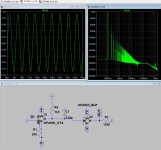
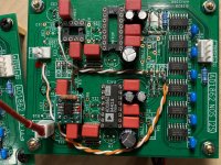
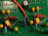
I have the 5v psu section dedicated to the I/V circuit to power the OPA860’s. Miro’s SIM circuit is populated under the pcb, the 250R bias resistor is mounted directly on pins 1-4.
I powered up the circuit without any chips installed to make sure the voltages were proper with no shorts anywhere, all was good. I installed one AD1862 and one OPA860 and powered up slowly with a variac. At 3.5vdc I measured 60mV of offset. At full power, 5.1 VDC, the offset dropped down to 15mV.
The 860 does get hot. At first, I thought I had a problem, but I think that’s just the way it is. I have IC chip heatsinks I can bond to them just as a precaution.
I listened briefly just to make sure there was no funky things going on, I did notice the volume is very low.
The first board I built had a 1K4 resistor installed at R9, then I increased it to 2K4 and it the volume is perfect. Will increasing R4 on the OPA SIM schematic have the same result?
Also, I reduced the 100R output resistor to 47R.
Attachments
Last edited:
Looks fine Vunce, temperature will be higher because the IC drops about 120mW (together with buffer). (R9 from the PCB has to be left unpopulated, because a different I/V is installed).
Also the change in R4 (in new I/V) increase the output voltage in the same way as the opamp I/V does.
When you disconnect the R9 (from PCB) then the output voltage should be higher (R4 and R9 were propably parallel).
Also the change in R4 (in new I/V) increase the output voltage in the same way as the opamp I/V does.
When you disconnect the R9 (from PCB) then the output voltage should be higher (R4 and R9 were propably parallel).
Last edited:
- Home
- Source & Line
- Digital Line Level
- DAC AD1862: Almost THT, I2S input, NOS, R-2R