Miro's DAC AD1862
Hi Folks,
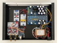
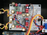
After some break, I can report that the DAC finally works. I ordered another 2 AD1862 chips as all other component worked correctly. It seems first 2 chips were damaged or I damaged them 😊
DAC plays extremely good – thanks Miro!
LM6171 is extraordinary opamp with superb low end. I love it. I just switched to ADA4627 – need more time but I think LM6171 is better. OPA810 is still to be tested.
VDRN regulator from Mark Johnson works very well without any oscillation for -12V rails (no need for 2R2 resistors in my case).
Cheers
Jacek
Hi Folks,
After some break, I can report that the DAC finally works. I ordered another 2 AD1862 chips as all other component worked correctly. It seems first 2 chips were damaged or I damaged them 😊
DAC plays extremely good – thanks Miro!
LM6171 is extraordinary opamp with superb low end. I love it. I just switched to ADA4627 – need more time but I think LM6171 is better. OPA810 is still to be tested.
VDRN regulator from Mark Johnson works very well without any oscillation for -12V rails (no need for 2R2 resistors in my case).
Cheers
Jacek
Attachments
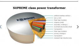
Regarding toroid transformers, Anatech are not very good. I took one apart to find out how they are made. The best off-the-shelf toroids for audio are probably the Supreme Audio Grade types from Toroidy. Their construction is much closer to high end custom made transformers such as some of those used by Pass Labs. Toroidal transformers SUPREME AUDIO GRADE V2 - Shop Toroidy.pl ...For best sound, one might try one or two larger core sizes than it looks like you would need based on expected operating current. On the other hand, going to too large a core size might be on the other side of optimal.
If not using a serious level toroid, probably R-core are better for dacs.
If not using a serious level toroid, probably R-core are better for dacs.
Attachments
Last edited:
I think, the important thing is that you induce (if this is the right English word, I mean the mag. field, measured in T) the iron core under it's capabilities.
For non tube electronics, where I do not need 2 almost identical secondary for tube rectifier, I prefer toroid, but from a good vendor who use quality core and also I instruct to design it 10-20% under "induced". Toroid has advantages, small, flat, flux to other circuits is low and in the toroid axle direction which is usually up and down, and normally we do not put circuit under and above the toroid transformer.
I also like the high quality small enclosed transformers from Gerth. I have good experience with them, and really bad with some other, same form factor transformers like the Hungarian made Makrai (I'm sad to say, but that it the truth.). Make sure you use the smaller power rated from the same form factor!
JG
Toroids have a very high bandwidth. They are great for passing RFI/EMI on power lines into sensitive electronics. For one thing they need a high quality internal electrostatic shield connected to power ground. The shield in Anatech are a few loose turns of magnet wire, not anywhere near a full shield. A better quality shield helps a lot with common mode RFI/EMI rejection, but differential mode noise is still up to the circuit designer to filter out. The RFI/EMI can sneak past filters and cause ugly sounding problems when it demodulated in bipolar input stages or demodulated by ESD protection diodes. It can then cause a dynamic shift in the bias of internal opamp nodes and a varying DC offset at the output. It can also intermodulate with the audio signal to produce ugly sounding audio. One symptom sometimes seen is that quality of power cords affects SQ, although that particular symptom is not always present.
On the other hand, R-core transformers can solve a lot of commonly occurring potential problems at low cost. There is excellent electrostatic isolation between primary and secondary windings. Also, they tend to have less differential mode bandwidth that toroids. Those characteristics are good for audio. They help make power supply design simpler and easier.
On the other hand, R-core transformers can solve a lot of commonly occurring potential problems at low cost. There is excellent electrostatic isolation between primary and secondary windings. Also, they tend to have less differential mode bandwidth that toroids. Those characteristics are good for audio. They help make power supply design simpler and easier.
Last edited:
Bandwidth more depend on the core materials, not the shape. Coil to coil coupling in R core can be smaller, but that has other disadvantages.
In any way, a well designed toroid is still better than an R core pushed to the limits of the core and vica versa. If you can under induce the R core, that may be the best for low power things like preamps, DAC etc., (if you have enough space in the box because the flux getting out of the core is much higher and normally in the direction of other circuits).
All I want to say, it is more important that the trafo is well designed and not pushed to the limits. If you look at the waveform of an over saturated trafo secondary, it is not sinewave, but something ugly with lots of harmonics. So, I think first is to avoid creating problems.
EMI comes after, if you have issues with. Where I live it is not an issue from the street, but I had problem sources in the house. My second hobby is HAM radio and I had to "repair" or exchange some power supplies to have relative silence. What I found, interestingly, not the big power hungry things but the fridge, a phone charger and things like that. In HAM, those are killing HF reception black and white, but it does effect listening to music also. Some time ago I did used good EMI filters at the mains input, but I found it has slight negative effect to sound. It is better to eliminate sources than try to filter. A friend tried to demo a great mains filter box to me some time ago, and it helped. But, after it proved it helps in his home, I went there with a handheld and a frame antenna. After disconnecting some bad power supplies, the sound was better without the filter box.
Of course, in a big house with neighbors, you may have no choice and you may have expensive equipment of the financial minister (wife) what is difficult to repair even with added lots of ferrite rings on the power cable.
JG
Decek, it's a very clean casing, kuddos ") . Well done for the R-Core traffo.
. Well done for the R-Core traffo.
Just a little detail perhaps: however a thing could be improved : if you flip the dac board 180° you can make very short link between the usb board and the dac board which can give subtle but hearable effects often (I2S and jitter live better when it's short) and it doesn' matter if the wires for the RCAs output are longers to acheive that.
@ Miro : could it be fun to link for the newbies some link towards several R-Core traffos ?
. Well done for the R-Core traffo.Just a little detail perhaps: however a thing could be improved : if you flip the dac board 180° you can make very short link between the usb board and the dac board which can give subtle but hearable effects often (I2S and jitter live better when it's short) and it doesn' matter if the wires for the RCAs output are longers to acheive that.
@ Miro : could it be fun to link for the newbies some link towards several R-Core traffos ?
I don't mind searching for R core transformers, I guess I just want to understand more about why they're so strongly preferable. I understand that at a large view they are efficient and reject AC noise, but I see companies like MHDT using toroids and Schiit using PC mount EI transformers, even in the Yggy. Obviously there are also plenty of companies using R cores too (Audio GD and Mojo Audio come to mind).
I suppose what I mean is that there must be some transformer models better than others in all designs and ways to use them all?
I hope this comes across as a question - I don't have firsthand experience and most of you know more than me
I suppose what I mean is that there must be some transformer models better than others in all designs and ways to use them all?
I hope this comes across as a question - I don't have firsthand experience and most of you know more than me
Last edited:
Iggy, I did not take any offense! I meant my comments honestly, I do think people know more than me and I am here to learn.
By the way, here is one R core tf that appears to be a good fit! 115V/230V 30W R-Core Shielded Transformer for Amplifier Preamp DAC 12V+12V 9V+9V | eBay
By the way, here is one R core tf that appears to be a good fit! 115V/230V 30W R-Core Shielded Transformer for Amplifier Preamp DAC 12V+12V 9V+9V | eBay
I am a beginner too but I experiment myself and let my ears ot bias decide for myself. Rcore works fine here from all I experienced. Second is classic traffo then last is toroid for the sound . Some uses toroid because it beams less but decide on spec and suppliers they find not by ears. YMMV.
Assuming the widding power distribution is balanced you have 30 VA ÷ (24 V+ 18 V) = 0.71 A per srcondary. Which is enough imho. If you parralel two secondary of the same voltage you keep the voltage and double the power so 1.42 A. If you wire in serie you have the opositt...double voltage but twice less power.
It is always better to have a power traffo just made for the max a load needs at max and no more if you can...of course not the opposit.
Last edited:
First Cycle -Memory distortion
Sorry… still using the reMarkable 2. It is a pricey little thing. It reminds me of how the price of real estate has gone up. Try buying one of the pyramids today… even the small one. And then there’s the cost of airlifting the thing from Egypt to take an orbit around the earth. I can’t see the profit! Fortunately for me the price of spam hasn’t gone up.
My earlier presentation focused on the inability of FFT and THD measurements to identify non-linear non-harmonic spectral components generated from non-linear transfer curves. This was specific to a 3rd harmonic component being proportionately connected to a fundamental frequency component on the output, both being exponentially related to the input sinusoid. This phenomenon can be further examined in relation to the 2nd harmonic being proportionately connected to a DC component, whereupon both are also exponentially related to the input. In this case, when an amplifying device contains a vessel to store electrons, such as a capacitor, the output can exhibit “memory type distortion”.
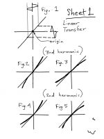
Non-linear transfer functions can take one of four basic types. These are shown in Sheet 1.
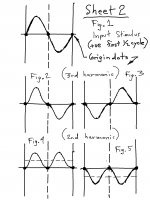
Figure 2- expansion up and down (generates 3rd harmonic)
Figure 3 - compression up and down (generates 3rd harmonic)
Figure 4 - expansion up, compression down (2nd harmonic)
Figure 5 - compression up, expansion down (2nd harmonic)
Sheet 2 shows the distortion waveforms resulting from an input sine impacted by the corresponding non-linear curves in Sheet 1. In all cases the isolated distortion waveform passes horizontally through the origin. If the input stimulus is considered to be made up of an infinite number of points with infinitely small time intervals the slope of the linear and curved transfer functions match each other in the interval between t0 (time 0) to t1 (the next time increment). Once the slope of the non-linear and linear transfer functions match there is no distortion, hence the distortion component alone must begin having zero slope or passing horizontally through the origin from t0 to t1. This also occurs for every half cycle.
The distortion waveforms show that the position of these waveform is not arbitrarily located, rather always smoothly (horizontally) connected between any sine stimulus regardless of being a half cycle, first cycle, last cycle, or any other cycle. Given a perfect amplifying device that is only affected by a non-linear transfer function there is no vessel of memory from any one point to the next point, regardless of being infinitely small. Hence for memory type distortion to occur requires a vessel to hold electrons and that the change in charge and discharge is disproportionate to the input stimulus.
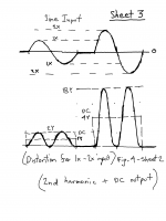
Figure 1 on Sheet 3 shows two sine inputs at 1x and 2x separated by 0x. For the transfer functions depicted in Figure 4 on Sheet 1, the 2nd harmonic changes exponentially at a 4x rate to that of an input sine changing at a 2x rate. Given the single sided nature of the distortion waveform the 2nd harmonic can be observed as reflecting a DC component changing proportionately with the 2nd harmonic, yet exponentially to the input stimulus. Hence this form of transfer function generates a non-linear DC spectrum component under circumstances of a changing input amplitude.
For “first cycle” or “memory type distortion” to exist requires that a vessel exists to contain electrons, and that such vessel charges and discharges those electrons in a non-linear way. Capacitor C1 in figures 1 through 4 on Sheet 4 is a vessel that can cause such memory distortion if the transfer functions of the amplifying devices take the form producing 2nd harmonics. In all cases both linear and non-linear DC components accumulate across capacitor C1. It should be noted that memory type distortion occurs for every level change of sine input, not just from zero input to the first cycle, and that this distortion is affected by the R1/C1 time constant being of variant affect by frequency and amplitude changes of the sine input. For this reason the phenomenon is considered an artifact of modulation that by any other name is still that.
Sorry… still using the reMarkable 2. It is a pricey little thing. It reminds me of how the price of real estate has gone up. Try buying one of the pyramids today… even the small one. And then there’s the cost of airlifting the thing from Egypt to take an orbit around the earth. I can’t see the profit! Fortunately for me the price of spam hasn’t gone up.
My earlier presentation focused on the inability of FFT and THD measurements to identify non-linear non-harmonic spectral components generated from non-linear transfer curves. This was specific to a 3rd harmonic component being proportionately connected to a fundamental frequency component on the output, both being exponentially related to the input sinusoid. This phenomenon can be further examined in relation to the 2nd harmonic being proportionately connected to a DC component, whereupon both are also exponentially related to the input. In this case, when an amplifying device contains a vessel to store electrons, such as a capacitor, the output can exhibit “memory type distortion”.
Non-linear transfer functions can take one of four basic types. These are shown in Sheet 1.
Figure 2- expansion up and down (generates 3rd harmonic)
Figure 3 - compression up and down (generates 3rd harmonic)
Figure 4 - expansion up, compression down (2nd harmonic)
Figure 5 - compression up, expansion down (2nd harmonic)
Sheet 2 shows the distortion waveforms resulting from an input sine impacted by the corresponding non-linear curves in Sheet 1. In all cases the isolated distortion waveform passes horizontally through the origin. If the input stimulus is considered to be made up of an infinite number of points with infinitely small time intervals the slope of the linear and curved transfer functions match each other in the interval between t0 (time 0) to t1 (the next time increment). Once the slope of the non-linear and linear transfer functions match there is no distortion, hence the distortion component alone must begin having zero slope or passing horizontally through the origin from t0 to t1. This also occurs for every half cycle.
The distortion waveforms show that the position of these waveform is not arbitrarily located, rather always smoothly (horizontally) connected between any sine stimulus regardless of being a half cycle, first cycle, last cycle, or any other cycle. Given a perfect amplifying device that is only affected by a non-linear transfer function there is no vessel of memory from any one point to the next point, regardless of being infinitely small. Hence for memory type distortion to occur requires a vessel to hold electrons and that the change in charge and discharge is disproportionate to the input stimulus.
Figure 1 on Sheet 3 shows two sine inputs at 1x and 2x separated by 0x. For the transfer functions depicted in Figure 4 on Sheet 1, the 2nd harmonic changes exponentially at a 4x rate to that of an input sine changing at a 2x rate. Given the single sided nature of the distortion waveform the 2nd harmonic can be observed as reflecting a DC component changing proportionately with the 2nd harmonic, yet exponentially to the input stimulus. Hence this form of transfer function generates a non-linear DC spectrum component under circumstances of a changing input amplitude.
For “first cycle” or “memory type distortion” to exist requires that a vessel exists to contain electrons, and that such vessel charges and discharges those electrons in a non-linear way. Capacitor C1 in figures 1 through 4 on Sheet 4 is a vessel that can cause such memory distortion if the transfer functions of the amplifying devices take the form producing 2nd harmonics. In all cases both linear and non-linear DC components accumulate across capacitor C1. It should be noted that memory type distortion occurs for every level change of sine input, not just from zero input to the first cycle, and that this distortion is affected by the R1/C1 time constant being of variant affect by frequency and amplitude changes of the sine input. For this reason the phenomenon is considered an artifact of modulation that by any other name is still that.
Attachments
Last edited:

Today I ordered parts for two PSU1 boards. Just as a heads up to all you fine people out there, the BOM for PSU2 is about double the cost as the BOM for PSU1.
I'm leaning toward PSU1 for the sake of simplicity and because MC78xx regulators seem fairly ubiquitous (Whammy headphone amp for instance)
I'm leaning toward PSU1 for the sake of simplicity and because MC78xx regulators seem fairly ubiquitous (Whammy headphone amp for instance)
Today I checked the stop-clock mechanism in the AN-207 application note from Analog Devices (the system used in diyinhk dac)
I thought "stop-clock" would mean that the clock is stopped for each channel and started only to populate DATA into each DAC buffer. The clock is stopped only for the second channel and it goes to the first channel all the time
I thought "stop-clock" would mean that the clock is stopped for each channel and started only to populate DATA into each DAC buffer. The clock is stopped only for the second channel and it goes to the first channel all the time
Attachments
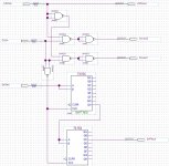
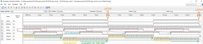
Stop-Clock I2S-to-PCM 20-Bit
Here I created the stop-clock for standard I2S (BCK 64fs), where both channels are stopped (but for simplicity they start a little earlier where first unused frame bits are discarded).
The big advantage to the AN-207 design is the unaffected Latch and the ability to connect to the standard I2S (Latch is unaffected also in my first design) and less ICs count.
3 or 4 ICs could be sufficient to create this glue logic
Attachments
Last edited:

- Home
- Source & Line
- Digital Line Level
- DAC AD1862: Almost THT, I2S input, NOS, R-2R