
Hi miro,
I am using 1k5 for R8/R9 and my oscilloscope tells me that I have 3 V peek to peek at maximum volume. Am I supposed to see 1.5Vp instead? How is the math done?
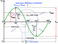
AD1862 DAC outputs +-1mA current (bipolar range = +1mA | 0 | -1mA). Math is:
Vp = I x R = 0.001 x 1500 = 1.5Vp
Vp is the half of Vpp, therefore Vpp = 2 x Vp = 2 x 1.5Vp = 3
Vrms = 0.707 x Vp = 0.707 x 1.5 = 1.06
Attachments
Last edited:
Just yesterday I was thinking that it would be nice to have a matching filter. No kidding.
My order from JLC hasn't shipped yet so I was able to add 10 filter PCB's for an extra $5 and I don't have to pay extra international shipping. So I am happy.
It would be awfully easy to install a toggle switch to flip the filter in and out. Easy filterless option!
My order from JLC hasn't shipped yet so I was able to add 10 filter PCB's for an extra $5 and I don't have to pay extra international shipping. So I am happy.
It would be awfully easy to install a toggle switch to flip the filter in and out. Easy filterless option!
@asilker
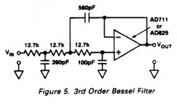
If you will play with this filter, please try these values(the first resistor 12.7k + capacitor 390pF install somehow on the PCB)
I'm currently running an F5 power amp which is remarkably broad-band, so I have strong motivation to investigate filters. I am waiting on PCB's and finishing this semester in grad school but I am interested in building up different filters
I have 10 filter PCB's on the way
Last edited:
Thanks!
That helped a lot. Now the only thing what I do not understand, what load resistance does the DAC see at the output? As I understood, the sweet point is somwhere at 270 Ohm for the 1865.
What resistance will it see in this circuit?
I'm confused to be honest how to do between the DAC and the headphone amp. Used a resistor and LL1527XL with great success, but the opamp way is grey area for me. Not in general, using opamps in non audio applications, but with this "portable" DAC I want to bring out the best possible from the AD1865.
Thanks!
JG
Thanks! As I understood, the sweet point is somwhere at 270 Ohm for the 1865.
As I know, 270Ohm is not a sweet spot for the Ad1865.. The ideal is 0R for all of the R2R Dac. Try to go down with the I/V resistor to 50Ohm or lower you will get better sound. Of course your output signal level will be also lower, so you need to “compensate” with another transformer ratio, 1-5 for example.
Summarize the Opamp I/V is much closer to the ideal 0R resistor than the 270 Ohm
When using resistor IV, the lower value the resistor, the easier it is for the dac current output to precisely force audio-signal current through the resistor. However, as the resistor gets smaller so does the audio-signal voltage drop across the resistor. So as a practical matter there is a trade off when selecting the resistor value.
AD1862 DAC outputs +-1mA current (bipolar range = +1mA | 0 | -1mA). Math is:
Vp = I x R = 0.001 x 1500 = 1.5Vp
Vp is the half of Vpp, therefore Vpp = 2 x Vp = 2 x 1.5Vp = 3
Vrms = 0.707 x Vp = 0.707 x 1.5 = 1.06
Excellent! Thank you miro! So I've got 1.5Vp for 1k5, exactly as the math dictates.
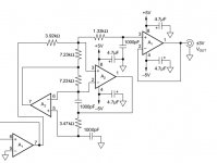
Can you guys look at this schematic please? Would I/V work this way? Any other idea?
Thanks,
JG View attachment sch.pdf
Thanks,
JG View attachment sch.pdf
When using resistor IV, the lower value the resistor, the easier it is for the dac current output to precisely force audio-signal current through the resistor. However, as the resistor gets smaller so does the audio-signal voltage drop across the resistor. So as a practical matter there is a trade off when selecting the resistor value.
Does this relate to THD?
I would guess that in this case, a more robust or isolated power supply could support higher Vp and low distortion?
Your limited by the AD1862 current output of +/-1mA, not psu.
Like Markw4 mentioned, for passive I/V (non-opamp), a lower value resistor will yield better THD (lower) but the compromise is lower output voltage. An output stage or buffer would be needed to sufficiently drive your next stage preamplifier or amplifier.
Like Markw4 mentioned, for passive I/V (non-opamp), a lower value resistor will yield better THD (lower) but the compromise is lower output voltage. An output stage or buffer would be needed to sufficiently drive your next stage preamplifier or amplifier.
Just took a look at the schematic and BOM at the first post. Based on my own dac experiments so far, guess I might try some different components in places, OPA1612 for IV, different wiring of opamp +-12v power, more filtering and then buffering after IV, and maybe a few other things if I happened to think of any. This would all be experimenting around to see what works best for this dac chip. Not sure what you guys have tried so far though. I would say that the little SMD film caps diyiggy uses for clocks can be used for bypass of other analog circuitry in a dac. That would include IV opamp bypass. NR1 and NR2 could be sensitive to cap sound, so I would probably try some film caps there probably with the capacitance values recommended in AD1862 datasheet, at least to start with. After the IV stage maybe another board with a couple of stages of passive RC filtering with through hole resistors and possibly SMD film caps (through hole resistors have more inductance, and smd caps have less of it; the combination might be more effective for filtering out RF. After the passive filter maybe a JFET or MOSFET buffer to remove any remaining DC and isolate the passive filters from downstream loads. Regarding +-12v power for opamps, I use the same regulators for both the + and - rails, for the latter rail using a positive regulator upside down, so to speak. That keeps power supply impedance verses frequency symmetrical across the rails. Also, I would only ground the +-12 rails at the dac board. That means the power transformer (preferably R-core) needs separate windings for each of those rails, a center-tapped secondary won't work for that. For electrolytic caps I would try Panasonic FM and or Panasonic FC over special caps branded for audio use. Those two caps sound different so one may be more suitable in some places and the other more suitable in other circuit positions. All component changes should probably be allowed to burn-in for at least 24-hours before judging the sound. Maybe even a week or two of burn in. If you think you might be biased or fooled by listening every day for changes, just don't listen for a week or so. Let the play music with the audio output disconnected. Experiments have shown all the above sorts of things can help sometimes. Up to people if they are willing to put in the work to do their own experiments.
EDIT: If you ever get dac working really well, it might be worth the expense to obtain real polystyrene caps for the audio signal path (beware of fakes). They sound a little more clean and clear than polypropylene. There are a couple of places I have sourced some from. One pretty well known source with a good reputation is Michaeal Percy Audio.
EDIT 2: Forgot to mention that digital volume controls before the dac are bad, with one exception: Digital volume controls should either be set to full maximum volume, or maybe a few dB lower if it helps distortion (some dacs have lower distortion if not driven quite all the way to full scale). Just have to try it and see. For the most part dac chips that have internal digital volume controls or else analog volume controls somewhere downstream after IV conversion may be found to give best SQ. That said, pots are a source of distortion too. Resistive ink they are made with is nonlinear, and so is the wiper contact with the resistive element. Better quality audio pots may be okay, but those may not be the cheapest. Switched resistor volume attenuators are probably best. Buffering with FET buffers may help prevent HF loss if the attenuator output is loaded too much by a downstream audio device.
Last edited:
Can you guys look at this schematic please? Would I/V work this way? Any other idea?
Thanks,
JG View attachment 999275
Sorry, I should have started another thread. Will do now.
Perhaps my silliest question yet:
PSU 1 + 2 BOM's ask for 12vac + 12vac
I understand this to mean two 6vac+6vac taps (12v between the taps). Is this correct?
Or in other words, am I looking for something like that which has 6v on each tap:
AS-0506 - 50VA 6V Transformer - AnTek Products Corp
Or something like this which has 12v on each tap:
AS-0512 - 50VA 12V Transformer - AnTek Products Corp
I've ordered from Antek before - your observation is right - BUT
The model numbers indicate the voltage on each cable, and that diagram is the only one I have seen on their site which lists one number instead of two -- suggesting that for some reason that illustration is measuring the Vdif instead of V to ground
Edit: It's a manufacturer document goof
The model numbers indicate the voltage on each cable, and that diagram is the only one I have seen on their site which lists one number instead of two -- suggesting that for some reason that illustration is measuring the Vdif instead of V to ground
Edit: It's a manufacturer document goof
Miro, I am considering it. I am finding plenty of threads where people here express that conventional wisdom is toroidals for power stages and R core for source and line stages.
I am having trouble finding any kind of measurement or direct comparison. Do you have any recommendations for what I should read to compare R core to toroids?
Editing to add: The Antek tf's have a static shield between primary and secondary, would this help reject noise from the primary side?
I am having trouble finding any kind of measurement or direct comparison. Do you have any recommendations for what I should read to compare R core to toroids?
Editing to add: The Antek tf's have a static shield between primary and secondary, would this help reject noise from the primary side?
Last edited:
- Home
- Source & Line
- Digital Line Level
- DAC AD1862: Almost THT, I2S input, NOS, R-2R