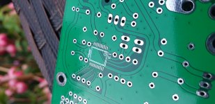
Fun experiments tonight with my son (especially his 20-something ears) and R8/R9.
For the test, I put different types of resistor in each side of the board and played mono versions of a number of different mp3s, ranging from Aretha's gospel album to Lou Reed to Sinatra & Pavarotti. I wired it all up a few weeks ago and completely forgot which side of the board went to which channel, so it was mostly blind up front. We used the balance control to switch between sides, and switched speakers side-side partway through in case they were individually contributing to the sound.
We definitely detected differences between a $0.11 Vishay metal film and an $11 General Resistance Squaristor, but to be honest it was hard for us to decide which was 'better'. The Vishay seemed to have more high end, maybe exaggerated, but with some music it made for a nice, lively presentation. The GR seemed to have less treble, maybe a little laid back, and was notably smoother, especially when Aretha really gets into it.
I think the GR is the winner for listenability here, but again - it was subtle. Others with refined palates might find more difference. If you'd like to try a pair of 1500R Econistors (slightly less expensive, similar specs) for the price of postage back and forth PM me.
It"s because of the type of OpAmp - some OpAmps have the current feedback and this capacitor will make them to "whisle")). AD811 for example..
Aha! I didn't know that.
I'm using AD844 at the output of PCM61 and using 2kohm i/v with 470pf cap from pin5 to ground..
Using 844's internal buffer.
Sounds wonderful
")
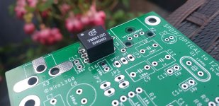
I got the small spdif optical boards today. Those 8804 will be fun to solder. That will test me. I've just done the 2sk209 fets on the BA2018. They seem easy looking at this!
Attachments
Last edited:
@jimk04 Be sure you add enough flux (rather more than less) and carefuly with the solder (rather less than more), with flux it is really simple
Hopefully everything will work properly, prepare for possible complications as you will be the first who is building it
Hopefully everything will work properly, prepare for possible complications as you will be the first who is building it
Last edited:
Lol, Diy... yes... I have a video of the wife going to the post office for picking myreceived shipments if you want
Looks like your wife is supporting you in this hobby. You paid everything with a card in advance, right?
Hello all,
To folks who have built this DAC using JLsounds I2S board, can you please check and let me know if there is any DC voltage on LRCK and BCK lines?
I see 0.8V on LRCK and 1.5V on BCK lines. This is V1 version of JLsounds I2S board. I am not sure if these voltages are expected.
Miro, is it ok for this DAC if there is DC voltage on LRCK and BCK lines?
Thanks
@baswamin - most likely your DMM is seeing the high frequency lines as DC (meter is confused and sees high frequency as DC).
Those figures look right - in fact this is a good way to see if something is being transmitted along i2s lines if you don't have a scope handy. It is useful to check LRCK, BCK, MCK lines and you will get a DC voltage. If no file is being played you probably won't get anything on the data line, but if you play a file you should see this fake DC voltage on the data line as well.
Fran
Hello Fran,
Thank you for your response.
The voltages I read on DMM is with USB connection floating (no wire connected). I haven't tried connecting to USB in laptop and check if there are changes. I will try and see if there are changes after connecting it.
I was concerned that this may cause some damage to the AD1862 chips since they are rare and in short supply, I want to make sure this is fine since these lines directly go to the DAC.
Thanks
Balaji
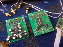
@miro1360 , @vunce I recently had time to build AD1865 DAC with the same PCB design and parts as mentioned in the thread, however I seem to be having one problem and that is I am getting sound out in only one channel.
Its very strange for me because its not just one circuit but two completed PCBs, using AD1865 and OPA627 from different batches both are original.
AMP is an older classic version Onkyo Integra 817RX, which I use normally with my Turntable. I have tried it with another AMP which is DENON PMA880R an A class mid level AMP which I use normally with my CD and Cassette player.
Just to make sure I am not doing something wrong I have used two different Amanero/XMOS boards but same problem.
Any ideas?
There is sound only in the right channel, left channel has oscillation, both DACs. On the sound side when I turn on the DACs with only the right channel working the sound is vibrant and "alive". One OPA627 in the right side DAC with white marking is really vibrant, this was the batch of 10 OPA627 which I bought from T.I official distributor, while ones with black markings I purchased from ebay by judging the output I think they are remarked.
Once I get both channels going I will test them with AD8610, Burson and Muse.
Could it be that I have connected the I2S in the wrong order?
Once I get both channels going I will test them with AD8610, Burson and Muse.
Could it be that I have connected the I2S in the wrong order?
I had a similar problem with a poorly soldered shift register on one of my boards and an inverted chip on another. The right channel data comes off the second shift register (IC2), so if something is wrong with registers IC3-IC6 the left channel will be blocked.
First thing to check: are all of the shift register chips aligned correctly? If one is upside down and you've powered up the board it probably will need to be replaced.
If the chips are all installed correctly, well soldered with no bridges between pins, you can check to see if data being passed between the individual chips. An oscilloscope will be very helpful, although you might be able to use a sensitive voltmeter.
With the board powered up and playing, carefully check for a square wave data signal on pin 13 (output) and pin 1 or 2 (input) on each chip. Go from left to right and you should find a place where data is not getting through the chain of shift registers.
BTW you can do all of this without the expensive DAC and OPA chips installed, perhaps reducing chances of damaging them with a badly-placed probe. In my own builds I always checked for the right voltages to the chip sockets before installing, and after the second time I messed up the shift register chain I made it a point to check for data flow, too.
Last edited:
@rehanabid Post a few detailed photos from your build
Did you use 74HCT164 shift registers (not the 74HC164), right?
Thanks for the reply I have used 74HCT164.
I had a similar problem with a poorly soldered shift register on one of my boards and an inverted chip on another. The right channel data comes off the second shift register (IC2), so if something is wrong with registers IC3-IC6 the left channel will be blocked.
First thing to check: are all of the shift register chips aligned correctly? If one is upside down and you've powered up the board it probably will need to be replaced.
If the chips are all installed correctly, well soldered with no bridges between pins, you can check to see if data being passed between the individual chips. An oscilloscope will be very helpful, although you might be able to use a sensitive voltmeter.
With the board powered up and playing, carefully check for a square wave data signal on pin 13 (output) and pin 1 or 2 (input) on each chip. Go from left to right and you should find a place where data is not getting through the chain of shift registers.
BTW you can do all of this without the expensive DAC and OPA chips installed, perhaps reducing chances of damaging them with a badly-placed probe. In my own builds I always checked for the right voltages to the chip sockets before installing, and after the second time I messed up the shift register chain I made it a point to check for data flow, too.
I reheated all the solder on the shift registers it, one feedback resistor on left channel had a problem replaced it and now at least one DAC had both channels working, this fixed the DAC board with capacitors soldered on the bottom side, but the other one still has problem, only one channel working. Will give Paddy Garcia's ideas a try, otherwise have got 8 other PCBs at hand.
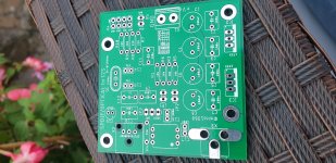
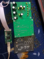
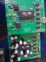
Here are few pictures of Miro's DAC and another design which is almost complete.
Attachments
Last edited:
Call it my stupidity, initially I soldered a simple 4 pin SIL, but later decided to put in a 5 pin connector removed the SIL with heat gun but in the process damaged the via, thats why the jumper.
Nonetheless, thanks to your previous post and investment in innova 3340 paid off, the culprit was a very small piece of wire underneath IC4, removed the IC cleaned the circuit, put in a new shift register and wow its working.
Thanks guys.
With one DAC running for almost 6 hours my initial take is that it definitely way better than HifiBerry DAC, slightly better than my XMOS-X7 not really at par with my Astell&Kern SP1000.
Compared to my AD1955 it sounds much better, I am using OPA627 as output buffers, in a few days will try AD8610, MUSE and Bursons.
This is definitely a DAC worth having.
Btw, there is on Mouser two close reference for this register; one is faster -20 n/s
IIRC- Does it change things from a listening point of view if one has to chose between the active registers VS a FGPA à la JLSOUNDS or IanCanada I2StoPCM ???
Always wondered the differences in term of noise, jitter, sound ?!
I'm populating the uf-l board with the PS2 reg and I'm wondering what strategy to use between all the different fron-end sources than sometimes I share with different dac... That will end with spending time to check the subjectives differences, knowing most of the time the difference is given by the different power supplies of these front -ends and also their passive parts.
- Home
- Source & Line
- Digital Line Level
- DAC AD1862: Almost THT, I2S input, NOS, R-2R