ARM Cortex M0 series CPUs have been around for about a decade now but, unlike their bigger siblings (M4, M7), don't come with I2S interfaces at the cheaper end of their product ranges. I decided to have a go at re-purposing the SPI interface which comes as standard on many low-end parts for I2S duty.
Over on Aliexpress you can find STM32F030-based boards for around $1 which have the necessary SPI interface. While its certainly cheap, the F030 is getting a bit long in the tooth now and has been superceded by the G030 which hopefully eventually will fall to the same (or lower) price as the F030. The G030 is a little bit more powerful (64MHz vs 48MHz) but more importantly is much lower power and also has a single I2S port. Even with the very welcome addition of the I2S port though you'll still need the SPI interface as the manufacturers in their wisdom only implemented a half-duplex I2S. Which means you can either use it for input, or output but not both.
To get started in programming the F030 you'll need to download a toolchain. ST has a helpful package called CubeMX which allows initialization of various peripherals by 'wizard', i.e point and click. After setting those up it generates code which users add their own individual elements to. In order to edit and augment the machine generated code, I use Keil's MDK which is free provided you're not generating more than 32kbytes. I avoid C as much as I can, preferring the embedded assembler capability. A debug probe is also a requirement - I use the debugger part of an STM discovery board which has been reprogrammed to emulate a Segger J-link. This handles programming the chip as well as debug functions such as single stepping and breakpoints.
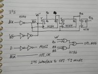
I'm attaching the schematic of the I2S->SPI interface which uses a handful of 74HC logic. Based on previous experience with an LPC1114 (also a Cortex M0) I reckon a 48MHz M0 can likely handle a 2X oversampling stereo FIR filter with a length no more than 90 taps or so. The G030 may well be able to deal with up to 120 taps. To go longer a second MCU could be used in dual-mono configuration or overclocking would be another option. Going beyond those options would probably require higher precision in MACs though so probably will be better suited to an M4 or even an M7.
As a sub-project on this thread I'd like to develop a plug-in replacement for the venerable old SAA7220 using the STM32G030. As far as I know, these are the only commercially available dev boards other than the official ones from ST : STM32G030???STM32G030C8T6????Cortex-M0??G0???STM-???
Based on the DS for the G030 the power draw should be under 50mW vs around 1W for the SAA7220, a 95% saving.
Over on Aliexpress you can find STM32F030-based boards for around $1 which have the necessary SPI interface. While its certainly cheap, the F030 is getting a bit long in the tooth now and has been superceded by the G030 which hopefully eventually will fall to the same (or lower) price as the F030. The G030 is a little bit more powerful (64MHz vs 48MHz) but more importantly is much lower power and also has a single I2S port. Even with the very welcome addition of the I2S port though you'll still need the SPI interface as the manufacturers in their wisdom only implemented a half-duplex I2S. Which means you can either use it for input, or output but not both.
To get started in programming the F030 you'll need to download a toolchain. ST has a helpful package called CubeMX which allows initialization of various peripherals by 'wizard', i.e point and click. After setting those up it generates code which users add their own individual elements to. In order to edit and augment the machine generated code, I use Keil's MDK which is free provided you're not generating more than 32kbytes. I avoid C as much as I can, preferring the embedded assembler capability. A debug probe is also a requirement - I use the debugger part of an STM discovery board which has been reprogrammed to emulate a Segger J-link. This handles programming the chip as well as debug functions such as single stepping and breakpoints.
I'm attaching the schematic of the I2S->SPI interface which uses a handful of 74HC logic. Based on previous experience with an LPC1114 (also a Cortex M0) I reckon a 48MHz M0 can likely handle a 2X oversampling stereo FIR filter with a length no more than 90 taps or so. The G030 may well be able to deal with up to 120 taps. To go longer a second MCU could be used in dual-mono configuration or overclocking would be another option. Going beyond those options would probably require higher precision in MACs though so probably will be better suited to an M4 or even an M7.
As a sub-project on this thread I'd like to develop a plug-in replacement for the venerable old SAA7220 using the STM32G030. As far as I know, these are the only commercially available dev boards other than the official ones from ST : STM32G030???STM32G030C8T6????Cortex-M0??G0???STM-???
Based on the DS for the G030 the power draw should be under 50mW vs around 1W for the SAA7220, a 95% saving.
Attachments
Last edited:
Appreciate your enthusiasm for cheap CPUs guys ")
Only last night I came across some ARM parts I'd not met before, from GigaDevices. That's a Chinese company that has been making almost-clones of STM ARM MCUs for a while now, but seems in some respects they're ahead of ST in that they have a Cortex M4 in a TSSOP20 package and they also have some of the latest microcontroller ARM IP in the form of the Cortex M23 which is also new to me. On Taobao the TSSOP20 Cortex M4 is just 3.3RMB i.e. under $0.50 in single quantities. The M4 has DSP extensions which make running filters more efficient - they claim almost 100DMIPs from this. The M23 part looks as low power consumption as ST's M0+ but I believe its a more powerful core - I'm going to spend some time reading the blurb on that this morning.
GD32 ARM Cortex-M23 Microcontrollers
Hi Bart
The FIR filter had a couple of functions - the primary one being 4X oversampling. The reason for oversampling is to move the image frequencies up in the spectrum in order to make them easier to eliminate by analog filtering. On a NOS DAC, images start at 24.1kHz (44.1kHz - 20kHz) but when you upsample by a factor of 4 with filtering the images start at 156.4kHz. That means a much less steep filter is needed. A secondary function of the filter was providing a bit of boost in the FR to allow a Bessel filter type to be used and still get a flat FR to 20kHz.
The FIR filter had a couple of functions - the primary one being 4X oversampling. The reason for oversampling is to move the image frequencies up in the spectrum in order to make them easier to eliminate by analog filtering. On a NOS DAC, images start at 24.1kHz (44.1kHz - 20kHz) but when you upsample by a factor of 4 with filtering the images start at 156.4kHz. That means a much less steep filter is needed. A secondary function of the filter was providing a bit of boost in the FR to allow a Bessel filter type to be used and still get a flat FR to 20kHz.
Happy to report that boards using STM32G030 are getting more affordable - now down to 16RMB ($2.3) here for the 32pin package : STM32G030K8T6???STM32G030????Cortex-M0+??G0???-???
I've only ever done FIR filtering with ARM Cortex M so far - I think the guy behind 'Audioweaver' has done the sums for what can be done with IIR, let me look into that and report back.
Its not a universal interface for SPI->I2S because the specific mode I'm using (TI mode) isn't supported on all SPI peripherals. But TI mode is available on SPI interfaces beyond these STM chips - some LPC (NXP) chips have it too.
Here's the DSPconcepts document I was thinking of. Its lowest complexity platform is Cortex M4 where he reckons about 16 CPU cycles per IIR stage. Cortex M0 will be significantly slower so let's assume more like 24 clock cycles for each stage. At 44k1 that would allow about 60 biquads mono or 30 stereo with a 64MHz clock rate. But just a guess.
https://dspconcepts.com/sites/default/files/pd8_beckmann.pdf
Last edited:
You can take the man away from Poundland but you can't take Poundland out of the man.
More affordable.....I think we're well beyond that. The Bluepill is plenty cheap enough.
Happy to report that boards using STM32G030 are getting more affordable - now down to 16RMB ($2.3) here for the 32pin package : STM32G030K8T6???STM32G030????Cortex-M0+??G0???-???
More affordable.....I think we're well beyond that. The Bluepill is plenty cheap enough.
Perhaps you don't have dreams of building a transversal filter-DAC which calls for a few dozen MCUs....
Over here the Bluepill is under half the price of any STM32G030 board (for single units) but its a relative power hog so doesn't lend itself quite so well to multi-MCU projects.
STM32F103C8T6 CS32F103C8T6 ??? ??? ??? STM32 ARM-???
Over here the Bluepill is under half the price of any STM32G030 board (for single units) but its a relative power hog so doesn't lend itself quite so well to multi-MCU projects.
STM32F103C8T6 CS32F103C8T6 ??? ??? ??? STM32 ARM-???
Last edited:
Multi-MCU dream DAC
About 8 years ago I built a transversal filter DAC - some pictures of it are shown on my blog : Prototype MOS DAC - diyAudio There are two parts to it - the digital, which is all shift registers and a bit of logic, and the analog which is DACs with weighting resistors on their outputs, after which all currents are summed.
The idea behind this DAC is fairly simple even though its complex to build with all those chips I2S normally has a bit rate which is 2X faster than necessary for RBCD in that it allows for 32bits per sample whereas only 16 are used, the rest are zeroes. I reasoned that if I could create a circuit which would double the WS frequency and de-interleave the two channels then the resulting waveform would look something like a zero-stuffed 2X upsampled I2S stream. If then that 2XOS stream were fed into a transversal filter then I'd have a 2X upsampler without needing any explicit DSP.
The transversal DAC in the picture (the 'tower') used resistors to create the individual DAC/tap coefficients. Which makes it rather inflexible - to have a different filter response, a different resistor array is required. What I figure doing with multiple MCUs is using them to implement digital multipliers so the whole filter can be configured in software. No need for any resistor array then, the multiply happens before the DAC rather than after it. Having a single MCU look after a local array of DACs means we can build filters as long as we like (or can afford) just by chaining together 'smart DAC' boards.
The STM32G030 CPU has a pair of SPI ports so I'm thinking if we build the DAC dual mono we can have 8 DACs (therefore 8 taps) per PCB. It will need a handful of shift regs (HC164s this time) to interface the SPI output to the DACs plus some muxes (HC153s). Ideally I'd like a PCB no larger than 5*5cm but that might prove too optimistic a goal.
About 8 years ago I built a transversal filter DAC - some pictures of it are shown on my blog : Prototype MOS DAC - diyAudio There are two parts to it - the digital, which is all shift registers and a bit of logic, and the analog which is DACs with weighting resistors on their outputs, after which all currents are summed.
The idea behind this DAC is fairly simple even though its complex to build with all those chips
I2S normally has a bit rate which is 2X faster than necessary for RBCD in that it allows for 32bits per sample whereas only 16 are used, the rest are zeroes. I reasoned that if I could create a circuit which would double the WS frequency and de-interleave the two channels then the resulting waveform would look something like a zero-stuffed 2X upsampled I2S stream. If then that 2XOS stream were fed into a transversal filter then I'd have a 2X upsampler without needing any explicit DSP.The transversal DAC in the picture (the 'tower') used resistors to create the individual DAC/tap coefficients. Which makes it rather inflexible - to have a different filter response, a different resistor array is required. What I figure doing with multiple MCUs is using them to implement digital multipliers so the whole filter can be configured in software. No need for any resistor array then, the multiply happens before the DAC rather than after it. Having a single MCU look after a local array of DACs means we can build filters as long as we like (or can afford) just by chaining together 'smart DAC' boards.
The STM32G030 CPU has a pair of SPI ports so I'm thinking if we build the DAC dual mono we can have 8 DACs (therefore 8 taps) per PCB. It will need a handful of shift regs (HC164s this time) to interface the SPI output to the DACs plus some muxes (HC153s). Ideally I'd like a PCB no larger than 5*5cm but that might prove too optimistic a goal.
Last edited:
I just came across this very useful article on understanding the fundamentals of FIR filtering - from the 'Filter Wizard' aka Kendall Castor-Perry. It's bound to come in useful when I get into designing filters for the architecture I'm designing.
Planet Analog - FIR fundamentals Part 1 - Analyze FIR filters using high-school algebra
FIR filter design software can be downloaded for free, I've had a play with ScopeFIR which lets you design filters up to 32taps in its free form for up to a month. Seems Cypress PSoC creator might offer similar design capabilities, I'm downloading it now (635MB) to see what it can do.
- Home
- Source & Line
- Digital Line Level
- Cheap ARM MCUs for RBCD audio