I'm using the A31 with a MCP16312 Buck-Converter. To avoid noise you should invest some time in appropriate filtering (PI-Filter, ferrit beads etc.).Has anyone found a good 24-32V to 5V DC to DC converter for the Arylic board? I’ll have either a 24 or 32 VDC power source for my amps and the Arylic docs state that their product needs 5 VDC @ 1 amp.
That's what I mentioned in post #25: -->Link.A sure Adau1701 DSP board could be hooked up to it with only some minor modifications removing the crystal from the board such that the master clock output from the Up2stream module can be connected to the DSP board. I am not sure yet of the clock frequency of the MCLK output.
I found out that the volume meta data (as well as play/pause state) is transferred via uart (and not i2c) from the A31 to the uC on the Arylic base board. I will decode the sequence when I find some time.
The uC on the arylic does the digital scaling/volume of the i2s data coming from the A31.
I found out that the volume meta data (as well as play/pause state) is transferred via uart (and not i2c) from the A31 to the uC on the Arylic base board
Ok, that is helpful. Do you know the frequency of the master clock output of the new Up2stream modules? The PLL mode for generating the core clock of the DSP may still be an issue. For the sure DSP board the default master clock should be 256 x fs. I'm not sure if this is the case when I use the Up2stream board to generate the master clock.
The mclk of the arylic board is 256xfs (11.2896b MHz). So with the standard PLL settings (12.288 MHz) of the adau1701 boards it will work without changes.Ok, that is helpful. Do you know the frequency of the master clock output of the new Up2stream modules? The PLL mode for generating the core clock of the DSP may still be an issue. For the sure DSP board the default master clock should be 256 x fs. I'm not sure if this is the case when I use the Up2stream board to generate the master clock.
Any news in this matter?I tried calling PE but couldn't get through to the right product manager. The person I talked to was going to get the information and email me back, so I'm in wait mode. I asked about availability of the A98, the A118 and A97L, plus whether there was some additional application data other than the "User Manual".
I thought about that clock master/slave issue again:
What we know so far:The A28/A31 doesn't do resampling. It is a renderer, and the server is what does the formatting and packages the audio for the right sample rate. Once the renderer specifies the audio format, the server keeps providing data packets as requested, and the renderer outputs it at the negotiated sample rate.
The Whitebear DMR Analyser lets you read back the supported formats and data rates and number of channels from the renderer, and it turns out the A28/A31 supports a wide range of formats and sample rates. The Whitebear tools lets you send data at different rates and various formats, and a lot of these can be played back by the A28/A31. However, there is a problem using the device as I described. The A28/A31 tells the server--whether it is Spotify or a DLNA server that it is outputting the data at 44.1KHz with 16 bits and 2 channels, but it has no idea what clock it is using. So if you provide a 48KHz word clock with a 3.072MHz bit clock, it will tell the server that it needs 44.1KHz audio but it will actually clock it out at 48KHz--about 9% faster.
But I'm curious whether the firmware on the A28 can be changed to tell the server that it needs to format the data as 48KHz 24bit data. I'll need to see if that data can be written to via the I2C interface. So this isn't done yet--drat.
- The specs of the arylic and linkplay products say they are capable of handling 24/192.
- From your observations with the Whitebear DMR Analyser we know the A28/31 modules are really capable of handling the higher quality rates and bitdepths. (?)
- The renderer specifies the audio format, but it doesn't do any input sample rate detection. Otherwise it would be working with the 48 kHz input clocks.
- The i2s clocks of the A31 are fixed, because the module runs as slave.
- The i2s clocks are set for 44,1 kHz.
- Airplay 1 usually transfers at a fixed rate of 44,1 kHz. But that protocol is also capable of transmitting at multiples of 44,1 kHz.
In consequence I come to the conclusion:
It doesn't make sense to me that the A28/31 modules run as clock slaves. During operation the sample rate could change if you play any high quality files or even when using airplay.
So far I don't see any other way to handle different sample rates in the system?
Last edited:
For anyone who's interested in connecting an ADAU1701 DSP to a desktop computer or laptop, I have been able to get the DSP working with a cheap PCM2706 USB to I2S board. The connection is essentially the same as with an Arylic Up2Stream module. I desoldered the crystal on the bottom of a sure dsp module, see attached picture, after which I simly connected the clock and data signals between the two boards. In this case the setup is limited to 16bit 48kHz which is not quite high-res but it sounds fine. In Windows 10 the volume slider does not function though, only software volume control works for instance in Spotify.
Attachments
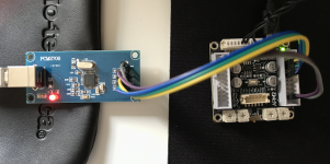
Yeah, those are the same connections I used to connect the Arylic I2S to my Sure board. The Sure DSP isn't my preferred 1701 board, but it does have the advantage that MCLKI is brought out to a connector. It looks like you surgically removed the crystal! Did you use hot air? I used a soldering iron which worked, but with less clean results.
On another note: Arylic has a new V3 version of its Up2Stream Mini board. The major additions are Bluetooth 5.0, an SPIDIF output and, if I read their ad correctly, the ability to stream music from a PC through the USB connector. Same price ($40) too.
On another note: Arylic has a new V3 version of its Up2Stream Mini board. The major additions are Bluetooth 5.0, an SPIDIF output and, if I read their ad correctly, the ability to stream music from a PC through the USB connector. Same price ($40) too.
On another note: Arylic has a new V3 version of its Up2Stream Mini board. The major additions are Bluetooth 5.0, an SPIDIF output and, if I read their ad correctly, the ability to stream music from a PC through the USB connector. Same price ($40) too.
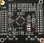
Interesting. Arylic tried to erase the lettering with the linkplay module name on the board.
But on one picture you can see they used a linkplay a31 module
")
It looks like you surgically removed the crystal! Did you use hot air?
I just used a soldering iron but I cleaned up the pads afterwards with some soldering wick.
I finally received my Up2Stream mini V2 module. The I2S interface works well in combination with a Sure Adau1701 DSP board, the I2S output also has volume control which can be controlled by both an IR remote and the 4stream app. However, there appears to be some kind of equalization with the default profile being rather overbassed. With the IR remote you can switch between different profiles but there never appears to be one where the sound is completely flat. It also seems like there is some algorithm active to widen the soundstage when AB compared to my first solution. With a good set of speakers this hurts imaging instead of improving it. Is there any way to turn this processing completely off?
Attachments
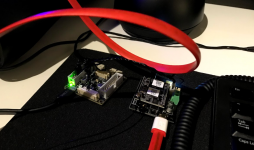
I haven't done some detailed tests of the audio quality of the A31 yet. But I would suggest to just use the Linkplay A31 without the Arylic base board. You could do the volume control in the DSP.Is there any way to turn this processing completely off?
@Neil Davis:
Any news on the availability of the newer generation modules from linkplay on parts express?
@Neil Davis:
Any news on the availability of the newer generation modules from linkplay on parts express?
They never got back to me. I could probably get the information I wanted and the pricing on other modules directly from Linkplay if I presented myself as a boutique audio business owner. I could do that through Audiodevelopers.com, but then I would have to sign an NDA and would no longer be able to share that information publicly. I don't want to go that route at this point.
Regarding your comments on the slave clock configuration: it makes perfectly good sense. The most common use case for these devices has analog output, WiFi input and analog input, where the clock is generated by the ADC. Using a clock from an output device (the ADAU1701 board) is possible, but it is not a common application and it's a bit of a kludge. Changing the DSP oscillator frequency to accommodate a specific input is not good practice.
A much better solution for connecting these modules to a DSP is to use a sample rate converter (ASRC). The ADAU1452/ADAU1466 chips have multiple ASRC's onboard to handle the conversion, and they can adapt to other sample rates with very low distortion. So the best answer for using the A31 with DSP is to use ADAU1466 boards. They are currently about twice as expensive than the ADAU1701 boards, but the price for the chip itself has dropped a lot and those boards will probably get cheaper as volume increases. The multiple ASRC channels will allow connecting to Bluetooth, USB and other digital sources without worrying about different clock rates.
Changing the DSP oscillator frequency to accommodate a specific input is not good practice.
A much better solution for connecting these modules to a DSP is to use a sample rate converter (ASRC).
Of course I could use an ASRC, but if we have a fixed output samplerate, going the "bit-perfect"-way seems to be the most straight-forward solution to me.
The point I want to make is that the specs of the module says:
"Decoding: Up to 24bit/192kHz".
So that is a clever marketing gag, because there is no possibility to use that higher sample rates on the output of the renderer. Maybe the module is able to decode high res files/content (it actually must be capabale of doing so when playing files from a NAS as flac is possible) but on the output everything will be resampled to 44,1/16.
To use the higher rates the renderer must either run as master and the hardware receiving that data must have an ASRC or the module runs as slave and requests a sample rate change during operation e.g. over uart (like the volume and play meta data is delivered).
Last edited:
The point I want to make is that the specs of the module says:
"Decoding: Up to 24bit/192kHz".
So that is a clever marketing gag, because there is no possibility to use that higher sample rates on the output of the renderer.
That's not a fair criticism. The spec sheet you are reading is for a developer, and if the developer provides a 192KHz clock and advertises to the server that it needs 24/192KHz data, that is what will come out of the module. At least, I assume that is the case--I tried 48KHz and the data came out fine (although not at the rate the server was expecting). Based on the Linkplay datasheet, if you provide a 192KHz clock and the server provides data formatted for 192KHz, everything should work and sound fine.
If a system integrator such as Up2Stream only provides a 44.1KHz clock, then their spec sheet should say that output is limited to 44.1KHz. But that's not Linkplay's fault. Up2Stream could have worked with Linkplay to get a software load that advertised other clock rates to the server and could have provided a way to use other clocks. But they didn't...they just chose to use a fixed clock and the "default" software in the A31. So Up2Stream may be guilty of a marketing gag, but the Linkplay datasheet is factual.
There are a lot of custom software loads for the Linkplay modules at this link: http://s000.linkplay.com:8020/wifi_audio_image_mcu/. Obviously, some system integrators are working with Linkplay to customize the modules, and I'm guessing that at least a couple of these vendor-specific software loads will allow using a clock other than 44.1KHz. And, of course, this software would need to publish the right clock rate to the server. That's why I tried looking at some of those files with a binary reader--I was hoping to find a table with MIME-types and associated sample rates. But I couldn't find anything in the short time that I spent on it, and moved on...
The specs I referred to are the ones from arylic. That is a product for the end user.That's not a fair criticism. The spec sheet you are reading is for a developer
Link - Arylic Up2Stream mini v3
As I mentioned in my post before the specs say: "Decoding up to 192/24". In fact that might be correct, but the end user assumes that the module is able to transfer the data (over i2s) at the native rates, which is not the case! But that's ok, because in the specs doesn't stand anything of the output sample rates of the renderer module (with its default firmware).
Of course that should be possible, but we are no OEM customers and therefore not able to change the firmware of the modules. So there is no other possibility as to use the modules as they are (with 44,1/16 setting).if the developer provides a 192KHz clock and advertises to the server that it needs 24/192KHz data, that is what will come out of the module.
You could provide any clock you want to the module and it would deliver data. There is no sample rate detection of the incoming clocks the renderer sees, so if you don't provide 44,1 kHz the data will come out fine, but at false rates. That makes the data/transmission useless.At least, I assume that is the case--I tried 48KHz and the data came out fine (although not at the rate the server was expecting).
How I see the whole "high-quality" audio thing:
44,1 kHz and 16 bit is CD quality, which is still the current reference. In my iTunes Library I use ALAC files. They are 44,1 kHz/16 bit (lossless) and Airplay transfers data in that format. So it is lossless and at its native rate! That is a bit-perfect transmission.
So everything is fine for me. Nobody will hear any difference between a lossless file at 44,1 kHz or at 96/192 kHz.
Last edited:
Yep--Arylic's specs are misleading. Even though the module may be capable of 24/192KHz output, Arylic hasn't provided the software and hardware support to make those sample rates possible.
I agree that 44.1KHz is not a major limitation for these devices, and I also understand the desire to change the crystal on the DSP to allow a direct connection to the ADAU1701 without resampling. It's a "clever" solution that is low cost and simple, and for some applications it is good enough. And it would be an even better solution if it was easier to replace the crystal on that cheap ADAU1701 board...
I agree that 44.1KHz is not a major limitation for these devices, and I also understand the desire to change the crystal on the DSP to allow a direct connection to the ADAU1701 without resampling. It's a "clever" solution that is low cost and simple, and for some applications it is good enough. And it would be an even better solution if it was easier to replace the crystal on that cheap ADAU1701 board...
And it would be an even better solution if it was easier to replace the crystal on that cheap ADAU1701 board...
Which brings up a question I have. I modified my 3e Audio 1701 DSP to use the MCLK from the Arylic motherboard. It works great, but it would have been easier just to replace the 3e DSP crystal with a 11.2896MHz with the same format.
So would that even have a chance to work? Two "master" clocks, but at the same nominal frequency. The 1701 datasheet states the "serial data clocks need to be synchronous with the 1701 master clock" which says no. But BCLK is divided down from the master clock by 64 so that certainly gives some leeway in clock differences. My guess is that it would work "mostly", but may suffer from occasional clicks from missed data.
No. All clocks in the signal path have to be synced (derived from one oscillator).So would that even have a chance to work? Two "master" clocks, but at the same nominal frequency.
When the dsp is the clock master, you could use just the linkplay module instead of the whole arylic up2stream. The linkplay module runs as slave and doesn't need a mclk, which makes wireing easier.
Agreed. I2S consists of serial data clocked by a bit clock (BCLK) and a word clock (LRCLK) and if the word clocks are out of phase, the bits won't be decoded properly. So having the clocks be close in frequency isn't sufficient: they must be in phase.
Sometimes I2S also includes a high frequency MCLK, which makes sampling at the middle of each bit easier, but not all I2S devices use MCLK. According to the I2S specification, what determines whether a device is a slave or master is which device provides BCLK and LRCLK. On the Arylic and Dayton boards, an analog to digital converter is used as the master--it provides the BCLK and LRCLK signals along with its serial data. When we "direct-connect" the ADAU1701 to the Linkplay module, we are using the ADAU1701 as the master, with BCLK and LRCLK generated at MP5 and MP4.
Sometimes I2S also includes a high frequency MCLK, which makes sampling at the middle of each bit easier, but not all I2S devices use MCLK. According to the I2S specification, what determines whether a device is a slave or master is which device provides BCLK and LRCLK. On the Arylic and Dayton boards, an analog to digital converter is used as the master--it provides the BCLK and LRCLK signals along with its serial data. When we "direct-connect" the ADAU1701 to the Linkplay module, we are using the ADAU1701 as the master, with BCLK and LRCLK generated at MP5 and MP4.
- Home
- Source & Line
- Digital Line Level
- Wiimu A31 module in combination with ADAU1401/1701 DSP