I've wanted to get some hands-on experience playing with circuits and such so I bought a USB 8 channel DAC kit and was hoping I could find some folks here that would be willing to guide me through the assembly. In exchange, I'm willing to write up the process as a guide for others in the future.
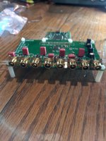
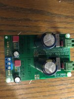
The board itself is an 8 channel ES9016 board here with this reclock between the USB input and DAC and the opamps here. I'm using this and this as the power supply.
My main questions are these:
1. What needs to be soldered and what does not? The site states "SMT components soldered, thru-hole components are not soldered", but it's not clear to me which is which. It is especially not clear how the opamps are attached to the board.
2. How consistent do the top/bottom lengths of the opamp pins need to be? For example, is it a problem that one side is longer as seen in the picture? Is it also ok if some opamps are connected by two sets of two pins (or one and three pins) instead of a single set of four pins? I had a lot of trouble resizing what was sent to fit.
3. What is the best order to approach assembly? Since the majority of my solder experience is with larger cables, I don't know what to expect when working with something this small.
4. How do I best go about getting power to each of the power supplies while minimizing the amount of outlets needed to power the DAC? I'd like to avoid having to provider a separate power outlet for each of the power supplies.
I'm sure there are more that will come up in the course of doing this, but any input on any of the above questions will be greatly appreciated. Thanks!
Attachments
Hi Mark,
Here are my brief comments:
1. If it says SMT components are soldered, that means that all the Surface MounT components are pre-soldered. This is good for you as surface mount components are more difficult. You should only need to solder the items with wire leads, like resistors, caps, and connectors.
2. They do not need to be exactly the same, but it is possible the longest lead will bottom out before the shorts make contact. If you are struggling to break them off at the correct interval, I suggest you use either two pairs of needle-nose pliers to do the snap, or a fine pair of wire cutters to make the cut. You can order additional headers for pretty cheap off of Digikey or SparkFun. The issue with using 1+3 or 2+2 is that they will be harder to align. You will probably burn your figures trying to hold it in place") /
/
3. Aways go smallest to largest components. Know your solder, iron, and flux. I use Kester red label, leaded solder that has water-soluble flux. You can also get the Kester water-soluble flux pen as well. Flux is like thermal butter that helps the two pieces of metal get to temperature faster.
4. You can power the two boards with the same cable if you wire it correctly.
Goodluck!
Here are my brief comments:
1. If it says SMT components are soldered, that means that all the Surface MounT components are pre-soldered. This is good for you as surface mount components are more difficult. You should only need to solder the items with wire leads, like resistors, caps, and connectors.
2. They do not need to be exactly the same, but it is possible the longest lead will bottom out before the shorts make contact. If you are struggling to break them off at the correct interval, I suggest you use either two pairs of needle-nose pliers to do the snap, or a fine pair of wire cutters to make the cut. You can order additional headers for pretty cheap off of Digikey or SparkFun. The issue with using 1+3 or 2+2 is that they will be harder to align. You will probably burn your figures trying to hold it in place
/3. Aways go smallest to largest components. Know your solder, iron, and flux. I use Kester red label, leaded solder that has water-soluble flux. You can also get the Kester water-soluble flux pen as well. Flux is like thermal butter that helps the two pieces of metal get to temperature faster.
4. You can power the two boards with the same cable if you wire it correctly.
Goodluck!
Thanks, Paul. I almost feel dumb after reading your response to 1. I didn't realize the site was saying SMT is pre-soldered. Now that part of it all makes sense.
Based on your recommendation, I've ordered better flux and solder and will practice quite a bit before getting starting. I've also ordered headers and will start over with those.
I hope to have some updates soon...
Based on your recommendation, I've ordered better flux and solder and will practice quite a bit before getting starting. I've also ordered headers and will start over with those.
I hope to have some updates soon...
I managed to get everything assembled, but I am only getting output from 5/8 channels. I couldn't find any info on how to attach the RCA jacks so I soldered them to the board, and that may be my issue, especially since it was a really bad soldering job. Any advice on troubleshooting?
Do you have an oscilloscope for troubleshooting? If not, you might be able to use an AC voltmeter or even a little audio amplifier such as a guitar amp for signal tracing.
There are normally 3 opamps per channel that convert the dac output currents into output voltages that would then go to the RCA output jacks. Don't know if you can identify any of that circuitry?
If so, you just play some kind of test signal or music through the dac and follow it from the dac to the RCA jacks. If it gets lost at some point, then your problem is right around in that part of circuit.
Hopefully, you have your opamps in sockets so that they are easily removable?
Otherwise, you could post some good, clear, well-focused, close-up pics of your work, the bad solder joints you suspect, etc., and let us take a look. Maybe we can see something that could be your problem.
I can identify the opamps themselves, but I don't know how to take the signal in or out of them. I could check for a signal with an AC voltmeter if I knew where to measure (no o-scope yet).
Since the files are large, here is a link to pictures showing the opamp and RCA soldering. It's certainly not pretty 🙂
Thanks for the help.
DAC - Google Photos
Since the files are large, here is a link to pictures showing the opamp and RCA soldering. It's certainly not pretty 🙂
Thanks for the help.
DAC - Google Photos
Those pics look pretty bad. What solder and soldering iron did you use (pics please)?
Looks like one of the opamps has its pins shorted together with solder. Also, some of the output connectors are not soldered at all.
You will need a proper solder iron for electronics work and proper solder.
In addition, you will need some solder wick for removing excess solder you have already applied. Some extra paste-flux would likely be useful for that process.
After we see what you are used for the existing soldering then we can figure out what you need to do next. You might that find watching some youtube instruction on electronics soldering would be helpful. A short movie I made to help people in another thread see how an opamp might be soldered to an adapter or PCB can be found at: Dropbox - SMD Solder.MOV ...You may notice that solder on the tip of the iron tends to move away from where you want to solder to go. That's because it goes to where more heat is, and since one side of the iron is touching the PCB that side if the tip is being cooled. If that happens you can do what I did which was to rotate the iron in my fingers to bring the solder around to where it could make contact with the PCB and opamp pin. Once the solder makes contact then heat transfer from the iron to the PCB and pin are greatly improved. As that area heats up then the solder will flow there. However, it needs to be done quickly to avoid burning up the flux that protects the solder from oxidation. One can practice such things with iron cold. Once you can manipulate the iron in the necessary motion, then try it with a test board and test component before trying it on your project board. You need some practice before risking damage to costly equipment. There is much more that can be said, but let's take it in small steps for now.
Troubleshooting with power turned on should only be attempted after all plainly visible problems have been fixed.
Last edited:
Thanks Mark and Paul. Note that the RCA portion looks pretty bad in part because I tried to desolder using a desolder gun without any wick so what you're seeing is a result of both bad soldering and bad desoldering. I haven't powered it back up since trying the desolder, and based on what you're saying, I don't plan on powering it back up until much later.
The opamps are connected to the board with header pins and not just straight through. This proved to be much more difficult than I thought for the reasons Mark laid out so I'll be sure and practice technique before attempting again. Since I was on a roll and having success with soldering other joints that looked good, I didn't use any flux for the opamps, and I've since learned the iron needed to be cleaned at that point - the solder kept bubbling up on the iron. In addition, the iron only came with one tip which is probably too large for the opamps, and I had trouble finding replacement tips to fit this one. I've since ordered a replacement set of tips which includes a smaller one.
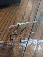
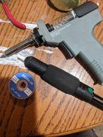
Assuming the next step is desoldering the opamps, any recommendations on what sort of wick I should use? (This is surprisingly hard to find - home improvement stores don't carry it.) Is what I have in the picture ok? When it comes to practicing technique on test components, any thoughts on where I can source such things in reasonable quantity for relatively cheap? Until I get a better understanding of these components, I'd prefer to see them in a physical store.
Also, is there any way to assess the likelihood of salvaging this board? I'm ok with replacing it since I started this project not to have a new DAC but as an excuse to learn to solder and learn a little more about how electronics work. With that, if anyone has any suggestions on other projects that are inexpensive, a good learning experience, and produce something useful, I'd love to hear it.
Thanks so much for the good advice and taking the time to walk me through this. Maybe someday I'll be able to contribute to the site beyond just asking questions
The opamps are connected to the board with header pins and not just straight through. This proved to be much more difficult than I thought for the reasons Mark laid out so I'll be sure and practice technique before attempting again. Since I was on a roll and having success with soldering other joints that looked good, I didn't use any flux for the opamps, and I've since learned the iron needed to be cleaned at that point - the solder kept bubbling up on the iron. In addition, the iron only came with one tip which is probably too large for the opamps, and I had trouble finding replacement tips to fit this one. I've since ordered a replacement set of tips which includes a smaller one.
Assuming the next step is desoldering the opamps, any recommendations on what sort of wick I should use? (This is surprisingly hard to find - home improvement stores don't carry it.) Is what I have in the picture ok? When it comes to practicing technique on test components, any thoughts on where I can source such things in reasonable quantity for relatively cheap? Until I get a better understanding of these components, I'd prefer to see them in a physical store.
Also, is there any way to assess the likelihood of salvaging this board? I'm ok with replacing it since I started this project not to have a new DAC but as an excuse to learn to solder and learn a little more about how electronics work. With that, if anyone has any suggestions on other projects that are inexpensive, a good learning experience, and produce something useful, I'd love to hear it.
Thanks so much for the good advice and taking the time to walk me through this. Maybe someday I'll be able to contribute to the site beyond just asking questions
Attachments

Best solder wick I have found:
https://www.amazon.com/Chemtronics-...?keywords=chemwick&qid=1573746362&s=hi&sr=1-1
For tip cleaning I prefer the brass brillo pad type (need to find/use clean spot on pad or replace pad for best cleaning), but wet sponges are sometimes an option:
https://www.amazon.com/Hakko-599B-0...words=hakko+tip+cleaner&qid=1573746501&sr=8-2
https://www.amazon.com/Thermaltroni...words=hakko+tip+cleaner&qid=1573746523&sr=8-4
https://www.amazon.com/Thermaltroni...d_r=V4GGQCTN766DSEXJ69RB&psc=1&qid=1573746551
Also, if more flux is needed for soldering or desoldering to help wetting, flow, and to protect solder from oxidation:
https://www.amazon.com/MG-Chemicals...al&sprefix=solder+flux+,industrial,207&sr=1-6
Correct solder for small joints (roughly 0.3mm diameter leaded):
https://www.amazon.com/Kester-Solde...3746689&s=hi&sprefix=kester+,tools,208&sr=1-6
Chances of salvaging the board look pretty good.
Some suggestions and comments: Use a bigger tip for solder wicking than for soldering, if possible. My rule with tips is use the largest and shortest one that fits (just barely not too big). That gives best heat transfer and fastest soldering. Soldering pads attached to a ground plane may require a bigger tip and more heat since the ground plane tends to conduct heat away quickly. Iron temperature is important, only a 5-degree difference in temp can make a big difference to soldering results. Different tips will conduct heat differently so may need to be set to different temperatures. I try to find the minimum heat to barely liquefy unleaded solder on commercial manufactured PCBs, then adjust heat up or down a few degrees until I find a temperature that can be used to unsolder or add leaded solder to existing joints. Sometimes adding solder first can help removal. When solder gets too oxidized it will not flow and can be very hard to remove. It may be possible to dilute it with fresh solder and maybe some extra flux.
Last edited:
It is important to understand what flux you are using. All solder and solder wick have flux added to it.
I only use Kester Leaded Water-soluble solder:24-6337-6401 Kester Solder | Soldering, Desoldering, Rework Products | DigiKey
If I find any other solder (besides lead-free water-soluble solder) in my lab I go and recycle it immediately. Not all solder is equal.
I use a water-soluble flux pen:83-1097-2331 Kester Solder | Soldering, Desoldering, Rework Products | DigiKey
You use it as a highlighter. You highlight the pin or pad you soldering.
As they are both water-soluble, you can clean the board by just rinsing it.
You will not be able to find a solder wick that has water-soluble flux. You will mostly find rosen core wick: 2-5L Chemtronics | Soldering, Desoldering, Rework Products | DigiKey
This is not too much of a problem, but if you use it you will need to clean the areas with alcohol, not water. A small paintbrush can help with cleaning.
The tip-tinner is important to preserve your tip quality. If I put the iron down for more than 10 seconds, I tin the tip. I always tin it before I turn off the iron. Soldering iron tips should be shiny, not dull. If it is dull, tin it. If solder will not stick to it, then it is possible that the tip is over oxidized. You can try sanding it with some fine-grit sandpaper or throw it away.
T0051303199N Apex Tool Group | Soldering, Desoldering, Rework Products | DigiKey
Basically, my process while soldering is:
1. Turn on iron.
2. Apply flux to the joint I will be soldering.
3. Pick up iron, and wipe it on the moist sponge.
4. Apply the iron tip to pin and then add the solder.
5. Tin my tip and put down iron.
6. Go to step 2. Repeat
Turning off iron?
1. Tin tip.
2. Turn off.
3. Clean board using water, blow-dry the board with compressed air. If you can get it all, use a heat gun on a low setting or an actual hairdryer to warm the board and evaporate all the water.
For flux cleaning I use:
https://www.amazon.com/MG-Chemicals...qid=1573751230&sprefix=isopro,aps,217&sr=8-15
And: https://www.amazon.com/ALAZCO-Brush...1_4?keywords=flux+brush&qid=1573751262&sr=8-4
The alcohol goes into a clear plastic cup, that sits inside a coffee mug (so the clear cup won't tip over easily). Once alcohol in plastic cup dries up, often the brush will be stiff with dried flux. In that case I replace the clear plastic up and the brush.
When cleaning flux off a board I put a folded paper towel under the board and hold the board up on its edge so that flux and alcohol will drip onto the towel.
Just pointing out there are multiple ways to solder and produce good joints.
One thing that may not have been mentioned yet is that solder should be clean and shiny before attempting to use it. I wipe it inside a folded paper towel until gray colored streaks stop coming off onto the towel. The cleaning needs to be done with each length of solder to be used. Don't squeeze the towel too tight around the solder or it will break off.
Also, the very thin solder I mentioned previously is for small joints like SMD parts or opamp adapter mounting pins. (It would have been much better if your opamps had the pins soldered only on the adapter end, socket should have been installed on the main board where the pins can plug in. That makes certain troubleshooting procedures much easier, for one thing.)
For larger joints on circuit boards I usually use about .6mm diameter solder. That's what I would use for the RCA connectors.
Basically, if solder diameter is too big then its very hard to get the right amount on small joints. On the other hand if diameter is too small it is hard to feed in the solder fast enough to get the soldering done quickly before the the first of the flux burns off.
While I've found IPA to be quite useful for everyday cleaning, nothing beats KONTAKT LR. I'm quite sure that this very product is not available over the ocean, there might be some substitute you're able to get. I'd say I need only 1/5 of that compared to IPA to get the same results.
Thanks for all the good info. I've ordered all the recommended items I don't already have that I can get here in the U.S. and will use these going forward. (Paul, based on your earlier post, I am the using Kester flux pin you recommended and Kester water soluble solder. However, I was using 0.031in (0.8mm) diameter solder and have now ordered 0.015in (0.4mm) diameter solder.) I've also made a note of all the recommendations on technique and process and will continue to practice those as well as watch more instructional videos.
Aside from practice, is my next step to remove the opamps. For this, will I need to remove them from the board entirely, or will I simply need to remove the solder I used to attach the opamps to the mount?
Mark, can you explain what you mean by this: "It would have been much better if your opamps had the pins soldered only on the adapter end, socket should have been installed on the main board where the pins can plug in"? I mainly don't know the terminology - what is mean by adapter end, and what is considered the socket here?
Mark, can you explain what you mean by this: "It would have been much better if your opamps had the pins soldered only on the adapter end, socket should have been installed on the main board where the pins can plug in"? I mainly don't know the terminology - what is mean by adapter end, and what is considered the socket here?
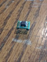
Pin headers can be soldered onto an opamp to dip adapter so that it looks like the one in the picture at:
SO8 to DIP8 Adapter | BrownDog 970601
Then instead of soldering those adapter pins to your dac board, you solder a socket to your dac board and plug the adapter-with-pins into the socket.
Mill-Max 8 pin DIP Socket
That way you can plug in the opamps to the dac board. It can be helpful if you want to remove the opamps at some point for troublshooting or if you want to try different opamps. (Remember not to plug/unplug opamps while the dac is powered on. That can damage things.)
Last edited:
Got it. I screwed that up then as it came with sockets, but I thought that was specific to a different set of opamps. Given all the mistakes I've made and the difficulty I've had in trying to redo the original board, I've ordered a new one. I hope to start on that this weekend. I hope that with the new solder tips, smaller gauge solder, and the other supplies I've picked up, after spending some time working on technique, this round will be much easier.
IME, even .4mm is a bit thicker than optimal for small SMD soldering (such as soldering opamps to adapters). Prefer .3mm for that, myself. For even smaller work such as soldering a broken pin back onto an IC there is some .2mm here, but only use that rarely.
That movie I linked to in earlier in this thread was with .3mm solder. Usually its easier for me to solder those than it looks in the movie. Its just that soldering under the digital camera was awkward. Since I'm old and can't see close up anymore without help, normally wear one of these: https://www.amazon.com/gp/product/B007CDJKM2/ref=ppx_yo_dt_b_search_asin_title?ie=UTF8&psc=1
If something is too small to see it with those then I go to: https://www.amazon.com/gp/product/B005C75IVM/ref=ppx_yo_dt_b_search_asin_title?ie=UTF8&psc=1 ...Unfortunately, looks like the price for one has gone up some.
Also useful:
https://www.amazon.com/Hakko-7-SA-S...prefix=hakko+twee,sporting,200&sr=1-3-catcorr
PREMIUM O.R GRADE AUTOCLAVABLE BARRAQUER NEEDLE HOLDER W/ NO LOCK 4" CURVED | eBay
Last edited:
Thanks again for all the recommendations. I've been able to get output on all channels with the new board using a test set of opamps that plug directly into the sockets.
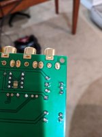
Next, I'd like to solder the RCA jacks to the board. Do I need to solder each 'leg' of the RCA jacks to board, or only some of them?
Next, I'd like to solder the RCA jacks to the board. Do I need to solder each 'leg' of the RCA jacks to board, or only some of them?
Attachments
Solder all the tabs on the RCA jacks, but best to use a larger solder iron tip to easily get enough heat in there so you can solder quickly without producing cold or oxidized joints. I use the same rule I do with screwdrivers (especially Phillips head !) which is to use the largest tip that fits (without being too big). For soldering the tabs, that would likely be a tip approximately the same width as the tabs are.
If no tip like that in your collection, you might check with a cold iron to see if you can fit a smaller tip in there laying on its side so that it makes good contact with tab and its solder pad along where to two meet at the edge of the via hole. That might work well enough, perhaps with the iron temp turned up higher than usual. Remember, the idea is to heat up the joint fast, solder quickly, and get out before the flux starts burning off too much. Yet, you need to stay there long enough for the solder to fully liquefy and flow freely. Always practice on scrap material if unsure.
If no tip like that in your collection, you might check with a cold iron to see if you can fit a smaller tip in there laying on its side so that it makes good contact with tab and its solder pad along where to two meet at the edge of the via hole. That might work well enough, perhaps with the iron temp turned up higher than usual. Remember, the idea is to heat up the joint fast, solder quickly, and get out before the flux starts burning off too much. Yet, you need to stay there long enough for the solder to fully liquefy and flow freely. Always practice on scrap material if unsure.
- Status
- This old topic is closed. If you want to reopen this topic, contact a moderator using the "Report Post" button.
- Home
- Source & Line
- Digital Line Level
- Guide me through assembling DAC board?