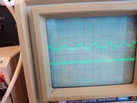
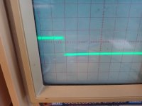
This is the at DEM pins at 820pF C measured after adding 2 x 20K from each pin (with 820pF in place) to the -18V power.
.
(I will try to find without 2 X 20K to -18V, but I am remember that is not good eye pattern and Fdem is smaller like 150KHz)
.
I found shot
.
(I will try to find without 2 X 20K to -18V, but I am remember that is not good eye pattern and Fdem is smaller like 150KHz)
.
I found shot
Attachments
Last edited:
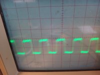
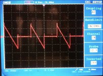
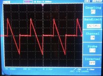
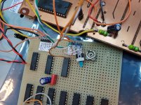
Big improvement on the data and BCK signal as you can see.
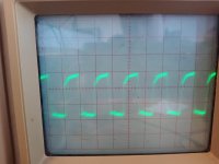
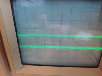
I decided that the latch and BCK signals were good, and to only experiment with series resistor for the data signal.
Your method was good Zoran : 220 ohms trimmer, and it ended up being approximately 96 ohms for optimal position with the least ripple.
My scope is only 20 MHz so the images are poor and not attached, but the amplitude of the ripple went from +/- 0,4 Volt peak to 0,2 V.
Definitely worth adding a 100 ohms resistor in both data signal leads.
For the fun of it I mounted a switch so I could A-B test the sound with and without.
First via my monitor system (DIY amp and DIY BBC LS3/5)... No difference detectable.
Then I pulled out my diy headphone amp and my precious and analytical Sennheiser HD 600s and listened.
First som folk/rock...push, push... Was there something? No.
Then some violins ...push...push... No, sorry but no difference detectable with respect to my limitations
Of course the two 100 ohm resistors will stay for good measure, but I don't think I will go down this path any further.
But thank you for the challenge Zoran.
Attachments
Yes this value for this logic fammily is almost the same that I trim to. AND this is much larger than generic values...
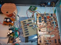
You right, using 20MHz scope. Probably with 1X @ probe selector. And that fren crocodile clip is probablu for ground, too distant from measuring taps? I think that maybe measurements are not showing real behaviour?
.
BUT more important is that You perform few listening tests")
.
And Decoupling Cs are made the difference
Thanks.
You right, using 20MHz scope. Probably with 1X @ probe selector. And that fren crocodile clip is probablu for ground, too distant from measuring taps? I think that maybe measurements are not showing real behaviour?
.
BUT more important is that You perform few listening tests
.
And Decoupling Cs are made the difference
Thanks.
Last edited:
Yes, only on the global supply.
I am not going to do more, it is fine.
Of course in a new PCB layout anyone can add all the caps they feel like.
...100uF black gate + 100nF MKP + 1nF paper-in-oil + 100pF Teflon.
Too all the IC s.
In case you think it would sound better.
(Sarcasm may be present)
I am not going to do more, it is fine.
Of course in a new PCB layout anyone can add all the caps they feel like.
...100uF black gate + 100nF MKP + 1nF paper-in-oil + 100pF Teflon.
Too all the IC s.
In case you think it would sound better.
(Sarcasm may be present)
@diyiggy
Thanks.
Studied the datasheet for a while... does not really make sense that it rarely clocks (how would the DAC chip even work without?!)
But I will put this in the box called:" too advanced for me at this time, so I will follow others advice!"
it clocks but not at the intended frequency, not locked at the expected frequency if you prefer (lost in vocabulary perhaps
, sorry for that!). Known fact with tda1541A & TDA1540. It works but not at the precision allowed and some said it could be heard with the best system (Think it comes from the ECDESIGNs thread). Some try to trigger with a scope, etc, as said in my post, unluckily it drifts due to the very low capacitance coupling.Maybe as you have a scope you can check outside of the box, your choice, of course.
Last edited:
Any JFET (pref. low noise) with Idss larger than 2mA. Say Idss=4-6mA or more.
From +5V power to Io dac pin.
I tried BF245B, 2SK170 etc.
But simple R could be used offcourse. Like in some Revox models.
Ok, thanks for that. I was not sure passive would be less noisy there and there was perhaps some impedance problem. I assume a cell with low impedance a la LiFoEtc 3.3 V with a resistor could be then an ideal solution ?!
Yes, only on the global supply.
I am not going to do more, it is fine.
Of course in a new PCB layout anyone can add all the caps they feel like.
...100uF black gate + 100nF MKP + 1nF paper-in-oil + 100pF Teflon.
Too all the IC s.
In case you think it would sound better.
(Sarcasm may be present)
Anyway for the the rest of the DEM matching legs, just choose the smallest inductance you can solder, so very close ground (no sarcasm
)Anyway for the the rest of the DEM matching legs, just choose the smallest inductance you can solder, so very close ground (no sarcasm
That was actually also my point.
Instead of focusing too much on decoupling the already well functioning CMOS logic, it might be better to focus on the caps for the DAC chip and the analogue stages.
Do you have a link for the ECDESIGN thread?
It's more about the layout ime, but at close inductance I liked acrylic/PPS smd caps more than ceramic class I, and 5 mm space-leads radial mkp are too much bulky, better to reduce the inductance ! Of course no problem for the DEM timing pins 8&9, you use KP from Wima, silver-Mica, C0G, in relation to what you have but avoid ceramic class II.
No sorry, ECDESIGNS reference was from my memory if it serves me well. But if you ask just a link for the thread itself and not the related post, it's all in the TDA1541 long thread 2 millions views in the digital line section.
No sorry, ECDESIGNS reference was from my memory if it serves me well. But if you ask just a link for the thread itself and not the related post, it's all in the TDA1541 long thread 2 millions views in the digital line section.
Last edited:
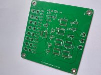
Seems it was made for the TDA1541A ! proof for the TDA1540 as well ? Not from ECDESIGN himself, at least the layout is not, the shematic I don't know ! Oh no... all those ceramic class II pads ! I prefer what you did with the through hole Class I, hey
I beleive the JLSounds is proof, maybe also the the I2StoPCM Iancanada board. But the last needs a MCLK injection and all uf-l cable.
the Philips SA chip thingy to do it all is bad ?
I beleive the JLSounds is proof, maybe also the the I2StoPCM Iancanada board. But the last needs a MCLK injection and all uf-l cable.
the Philips SA chip thingy to do it all is bad ?
Last edited:
Indeed I have both, but at 1206 case size this is not what I will putt for my own at some areas (though C0G exists)... Notice on the boards you are talking about caps are way littlier must of the time, 04 size is not rare on them... so class II, hey !
@ Miro, so do I, while there are cool smt as well usefull (think inductance and magnyfing glass ), so frankly I will not use X7R for the DEM element matching network... everyone being free of his DIY toys at the end of course - YMMV -
@ Miro, so do I, while there are cool smt as well usefull (think inductance and magnyfing glass
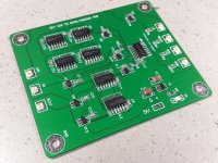
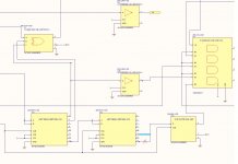
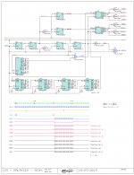
), so frankly I will not use X7R for the DEM element matching network... everyone being free of his DIY toys at the end of course - YMMV -This is for 16bit Time Sim format from EC design.
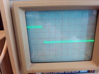
(As we can se LE line is intact. Like maybe most important line.)
.
It is stopped bit cloc operation. And design i working. Some members are build this circuit i think?
.
For 14 bit, with TDA1540, maybe only intervention will be to change pin at 4060 from Q4 pin 5 (16bit) to Q3 pin 7 (8bit). AND ADD 6 bit count or shift to 14bit?
.
Attachments
- Home
- Source & Line
- Digital Line Level
- TDA1540 - I2S to Offset Binary, no CPLD, no FPGA