Hi, JohnW. Thanks a lot for your comment. ") We are a climber who wants to reach the summit, i.e., -120dBFS noise floor, from another route. I'm a simple person who believes in a real PCB. PCB is always my guru who teaches me a lot. When my PCB has excellent performance, it's real and correct for me even if it has some paradox with the theory.
We are a climber who wants to reach the summit, i.e., -120dBFS noise floor, from another route. I'm a simple person who believes in a real PCB. PCB is always my guru who teaches me a lot. When my PCB has excellent performance, it's real and correct for me even if it has some paradox with the theory.
BTW, I agree with you these are dominating factors of 1bitDSM, though I have a little bit different opinion about 1.
As to 2., I'm very interested in your approach. This is an essential point to achieve a low noise floor. Mine is a differential amplifier in saturation mode. I called it as ECL several times, but ECL may result in misunderstandings. It acts as a current switch to convert the DSM signal into an analog one without the interference from the dirty digital side. The functionality itself has nothing to do with ECL. It apparently seems fine as intended. Could you share the way you take to isolate the digital noise?
We are a climber who wants to reach the summit, i.e., -120dBFS noise floor, from another route. I'm a simple person who believes in a real PCB. PCB is always my guru who teaches me a lot. When my PCB has excellent performance, it's real and correct for me even if it has some paradox with the theory.Ignoring the Digital noise sharpers, the noise of the 1bit DAC is dependent on :-
1. Jitter / Phase noise of the Clock (and isolation to this noise provided by the Relatching logic).
2. PSU noise on the DAC Array
3. Thermal noise of the components in the DAC array
4. Noise of the analogue circuit after the DAC Array.
BTW, I agree with you these are dominating factors of 1bitDSM, though I have a little bit different opinion about 1.
As to 2., I'm very interested in your approach. This is an essential point to achieve a low noise floor. Mine is a differential amplifier in saturation mode. I called it as ECL several times, but ECL may result in misunderstandings. It acts as a current switch to convert the DSM signal into an analog one without the interference from the dirty digital side. The functionality itself has nothing to do with ECL. It apparently seems fine as intended. Could you share the way you take to isolate the digital noise?
So we are do things rather different, using CMOS logic as it has lower Phase Noise, and higher voltage swings.
In the attached image you can see a development PCB we are currently working on with a simple SDM discrete DAC array and FPGA modulator (Digital filtering is performed by the large XMOS which also supports MQA unfold, USB and System control etc).
This design has a galvanically isolated analogue stage, not because it helps measurements, but because in practical use isolating the USB Host ground from the Analogue system saves a whole bag of hurt with hum loops etc..
The Discrete clock stage is located between the discrete DAC arrays for shortest signal path, the SDM signals from the FPGA are resynchronized to this MASTER clock, before being fed into the DAC array.
The clock is isolated and fed back to the Digital section / FPGA / XMOS etc.
The clock circuit has an ultra low noise semi discrete regulator. Due to space constants, the DAC arrays are powered via an ES9311 Low noise regulator. If space allowed we would have preferred to use a semi discrete regulator design as used for the Master clock - but the ES9311 is not that bad, importantly in can be designed to provide "active" regulation across the whole audio B/W which is very important to avoid "capacitor sound"...
The resynchronization stages have there own regulators and LC networks to help isolation between stages.
The two transformers provided very low noise isolated supply to each channel - these are synchronized to the Audio master clock (the low Phase noise provides a low noise DC output) to prevent unwanted noise products folding back into the audio band, and despite there size they can provide 1.5A each! - infact all switching supplies in the digital section are also synchronized to the audio master clock.
The DAC array supports SDM to x512, so native DSD can be routed to the DAC array without re-modulation.
Dropbox - Discrete DAC Stg6.png
Last edited:
An easy assumption to make, but what is important is the frequency content (Spectrum) of the PN.
Communications / Data systems set there PN measurement corner frequency too high for audio applications - typically 12KHz or higher, making there Jitter specs. useless for audio applications - most systems have VERY poor close in phase noise due to high PLL BW, poor oscillator Q, noisy low power logic design, etc.
If you look at the PN performance of Logic family's I attached ealier you can see that ECL has worst Close-in Phase noise compared to most CMOS family's, bench testing shows LVDS is even worst.
To get a better understanding of the "ball park" Jitter performance we require with Simple Maths (There are many factors that determine the absolute jitter requirement, but such basic math gets us more or less in the correct "Decade"):-
1 bit SDM at x128 FS= 5.6448MHz = 177nS
Lets set a target of 120dB Dynamic range (1 millionth), so we need to be able to reproduce our pulse stream with a short term timing accuracy of 177nS / 1,000,000 = 177fS
177fs assumes 100% modulation, at max we have say 50%, so:-
177fS/2 = 88fS
88fS is a crude "Off the cuff" calculation and does NOT take into account many details, but its a good starting point to appreciate the Jitter requirements to achieve 120dB DR with a pure 1bit system at 128FS...
Moving average DAC array arrangements / higher SDM bits ease these PN requirements, but thats getting into the finer details...
The point is you need to forget shooting for pS short-term jitter performance, but you need to be in the low fS range...
"Short-term" means over say 5 - 10 seconds to bring the Close-in noise slope (area) down to a decent level...
What I'm trying to impress upon you is that the typical Jitter performance corner frequency spec'ed from 12KHz is useless for our discrete Audio DAC array applications - you need to be thinking about timing accuracy in a different realm to normal industry standards (In B/W and level).
Measuring Close in Phase noise with the required Dynamic range is extremely difficult and expense - when higher performance measurements are required, we have a whole RACK of computer controlled equipment to performance the task, but the system still sets the industry standard for close in Phase noise measurements (the system has been upgraded since the picture was taken):-
Dropbox - Phase nosie measurement system.jpg
Heres the systems confidence test (basically the systems Noise floor):-
Dropbox - Agilent E5500 System Confidence Test.jpg
(Again the Mains related spuire is due to magnetic coupling of background fields into the system).
I said once before here on this forum that working with Discrete SDM DAC design is frustration but also the most educational experience a "Digital" audio designer can undertake
If and only if the jitter only shifts the output signal, close-in noise would be the least of my worries in a sigma-delta system. The jitter then only phase-modulates the sigma-delta modulate. As long as the phase deviation is small (<< 1 rad), close-in phase noise then only causes skirts around the desired signal - which get masked quite well by the mammalian auditory system, and besides, a given amount of time variation only corresponds to a very small phase deviation when the signal frequency is low. Far-off noise, on the other hand, modulates some of the huge out-of-band quantization noise into the audio band, thereby raising the noise floor.
However, things can be more complicated depending on the exact DAC design, and phase noise may not be the correct metric. For example, suppose a clock signal with a finite rate of change goes through a buffer with a trip level that shifts up and down slowly because of the buffer's 1/f noise. The rising and falling edges will then be affected in opposite directions - when the trip level is temporarily a bit higher than average, the rising edge gets delayed a bit extra while the falling edge gets delayed a bit less. The fundamental frequency component stays essentially in place, so a phase noise measurement will hardly see any effect, but a sequential circuit that only looks at the rising edges will be affected, and anything that's sensitive to the duty cycle will be affected much more.
As an example of a DAC that would suffer a lot from low-frequency duty cycle variations, take my single-ended single-tap flip-flop and NOR gate RTZ DAC, the one that you don't like and that I only use occasionally for its simplicity when I don't care too much about noise. It has an output DC level that depends directly on the duty cycle of the clock, so low-frequency duty cycle variations directly translate into low-frequency output noise. Make a two-tap FIRDAC version of the DAC (with equal weights) and/or a balanced NOR/AND version, and the effect is solved or at least much reduced.
xx3stksm uses NRZ DACs, so he won't be sensitive to duty cycle variations to begin with. Of course NRZ has problems with differences between low-to-high and high-to-low delays, but those are cancelled to some extent by using differential signals.
Nonetheless, I'm as surprised as you are by the great results xx3stksm gets using the FPGA's output flip-flops.
Last edited:
If and only if the jitter only shifts the output signal, close-in noise would be the least of my worries in a sigma-delta system. The jitter then only phase-modulates the sigma-delta modulate. As long as the phase deviation is small (<< 1 rad), close-in phase noise then only causes skirts around the desired signal - which get masked quite well by the mammalian auditory system, and besides, a given amount of time variation only corresponds to a very small phase deviation when the signal frequency is low. Far-off noise, on the other hand, modulates some of the huge out-of-band quantization noise into the audio band, thereby raising the noise floor.
You say close in phase noise is masked by the signal, but I find it effects the sounds stage presentation and general presentation of Bass (I hate to use this expression, but the foot tapping ability of the system)... Phase noise is not generally heard as discrete tones (unless you have a real problem), but impacts sound stage, Macro details, sibilance on female vocals etc.
For some reason I don't fully understand - left / right sound stage is the first to collapse in the presence of Jitter - although we have a few working ideas...
The presences of correlated jitter results in a fatiguing / hard sound (an all too common vice of digital systems).
Jitter is a complex beast and cannot be summed up as a simple number, its the PN spectrum thats all important, and each DAC topology has different sensitivitys to this spectrum...
The trouble with the FPGA outputs is that they are VERY heavily correlated with the internal processing patterns - the ear is AMAZINGLY sensitive to correlated jitter... These jitter components can be just below the noise floor which time aligned averaging will expose, yet they still effect the audio reproduction, the brain is an amazing system!
...the brain is an amazing system!
True, or potentially true. Perception seems to depend a lot on the individual and on the nature of prior listening practices. All IMHO, of course.
Jitter is a complex beast and cannot be summed up as a simple number, its the PN spectrum thats all important, and each DAC topology has different sensitivitys to this spectrum...
The sidebands around the desired signal I was writing about are both very small and independent of the DAC topology. On the other hand, the sensitivity to low-frequency duty cycle variations and to far-off jitter are very dependent on the DAC topology.
You say close in phase noise is masked by the signal, but I find it effects the sounds stage presentation and general presentation of Bass (I hate to use this expression, but the foot tapping ability of the system)... Phase noise is not generally heard as discrete tones (unless you have a real problem), but impacts sound stage, Macro details, sibilance on female vocals etc.
For some reason I don't fully understand - left / right sound stage is the first to collapse in the presence of Jitter - although we have a few working ideas...
The presences of correlated jitter results in a fatiguing / hard sound (an all too common vice of digital systems).
Jitter is a complex beast and cannot be summed up as a simple number, its the PN spectrum thats all important, and each DAC topology has different sensitivitys to this spectrum...
The trouble with the FPGA outputs is that they are VERY heavily correlated with the internal processing patterns - the ear is AMAZINGLY sensitive to correlated jitter... These jitter components can be just below the noise floor which time aligned averaging will expose, yet they still effect the audio reproduction, the brain is an amazing system!
I've found no actual evidence of this need to minimize the close-in phase noise for audible purposes. Do you have any links to any testing that's been done? Just curious, if not that's fine. I'm not going to go on endlessly about it not being audible or anything.
Last edited:
So we are do things rather different, using CMOS logic as it has lower Phase Noise, and higher voltage swings.
In the attached image you can see a development PCB we are currently working on with a simple SDM discrete DAC array and FPGA modulator (Digital filtering is performed by the large XMOS which also supports MQA unfold, USB and System control etc).
Thanks a lot for your pic. It's exciting to me. My impression is that you have fewer components than I imagined. It's probably because of different DAC topology you employ. Do you use RTZ? I also tried RTZ but failed. Analog FIR can't coexist with RTZ. My conclusion is NRZ is more friendly with analog FIR than RTZ at least. Next PCB I'm planning has at least 32taps, which results in many discrete components. One tap consists of three transistors and five registers. 32taps analog FIR equals to 96transistors and 160registers with 4mAx32=128mA !!!
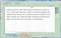
I must investigate the exact reason for the oscillation before going to next step. BTW, I employed a differential amplifier to isolate digital noise. It was a successful result more than I expected. If I force output drivers for transistors to stay H or L, which is defined as "static zero," residual noise of DAC includes those of analog circuit but has no DSM related noise. Pic. 1(-121.3dBFS) is the best scenario I could have in my DAC topology while I actually have(dynamic zero) is -116.3dBFS. In other words, I have still 5dB headroom for improvement.
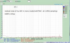
Furthermore, you must adjust the values because the residual noise of my ADC degrades the values. From pic.2, real performance in static zero is probably -124dBFS and dynamic zero is -117dBFS. So, the headroom is 7dB. It's astonishing to me. I would say digital isolation was luckily ideal.
Attachments
xx3stksm uses NRZ DACs, so he won't be sensitive to duty cycle variations to begin with. Of course NRZ has problems with differences between low-to-high and high-to-low delays, but those are cancelled to some extent by using differential signals.
As long as I have experienced on my noDAC PCB, some jitter on the clock doesn't degrade the noise floor. As you wrote, NRZ is very sensitive to the difference between low to high and high to low. I need to adjust the difference with the phase adjustment function of PLL inside FPGA. But the clock with variable phase(used for high to low) has a little bit large jitter than the fixed phase clock(used for low to high). It's not impossible to use the fixed clock for high to low. I was looking forward to seeing a better result than the variable one. But I couldn't find the difference between them. So, I now use the variable phase clock for high to low. I'm sure the sensitivity to jitter depends on DAC topology. My noDAC isn't so sensitive to clock jitter. The fatal factor is phase alignment between 24taps. At least up to x128OSR, clock jitter is the 2nd in my topology.
It's a very interesting question, especially for 1bitDSM. If your DAC is multibit, There is no worry about amplitude dependency from my experience on 3bit or 5bit DSM. I'm sure from -40dBFS to -60dBFS is a challenging zone for 1bitDSM. My noDAC also has such a weak point. I can post the FFT plot, of course. But it's very difficult to exclude intentional selection to show you better performance. Honestly speaking, I also can't predict which one is real or fake. Measured data is not always the same. 6db variation probably exists. I will post the plot later, the best one and the worst one. 
5 or 6 years ago I started fiddling with "no dac dacs", and I had a hard time figuring out what it was that made those strange noises at lower levels when playing certain music. Classical music etc faded into or started noisy, sometimes with whistling tones etc. I couldn't see it with all the -6dB test signals I used and not a lot of diy-ers here reported having those issues at all.
Sometimes I even made the problems worse despite having better snr and thd readings. When I did more online research (instead of just blindly measuring at high signal levels and trying all sorts of flip flops, filtering etc) and found out about the nrz and rise and fall time issues, the issues could be dealt with. I also found that when using a nrz dac it is sometimes best to aim for the best fidelity at those lower levels, the high signal levels scale well accordingly and one can choose between trade offs between them later. That and the rise in noise floor are imho the main indicators of good sound.
For now I also settled with cml logic, but mainly because it's easier to deal with a simple fast, sort of ideal nrz building block (rise and fall time are under 20pS) and learn from that than to incorporate all sorts of tricks with caveats regarding clock symmetry etc. That's for later.
Btw, with your fpga: isn't it really easy to program some form of rtz encoding as well as have the pll generate the necessary clocks for that?
I've found no actual evidence of this need to minimize the close-in phase noise for audible purposes. Do you have any links to any testing that's been done? Just curious, if not that's fine. I'm not going to go on endlessly about it not being audible or anything.
First its important to differentiate deterministic Jitter and non deterministic jitter, both effect the system in different ways.
So based on our experience, non deterministic jitter (such as shot noise in the XO) is a bit of a confusing one, lower does not necessarily mean better, it changes the balance of the sound and then you start running around in circles like a see / saw effect "this sound better but then we lost..."
We have circuits that reduce the Close in phase noise of XO circuits by about 20 to 40dB, but find that we prefer without (so higher close in noise) - its REALLY important to stress that this noise follows the classic 3 slope curve one sees in text books (so we are not talking about deterministic jitter).
With deterministic jitter, if its Data related then its universally bad, but if its say AC hum components (50/100Hz etc) then they have the effect of adding more "Bass Body" - even if they are very low level (say -130dB), when they are removed the sound becomes lighter... while having known hum components is "technically" bad, it becomes a matter of frustration that I can tend to prefer the sound with them - it becomes a question of balance...
We spin so many designs that after many years we start to see clear patterns, its becomes so obvious that we don't tend to question the fact, but only work to resolve with known solutions...
We are lucky in that we can directly measure phase noise etc. and by measuring and listening we can form patterns - you do something for many many years and even the most non interested will see patterns, even when not looking for them or expecting them... Its more interesting when these patterns don't follow the expected result (such as lower hum components = lighter bass)!
I've come to appreciate that the hardest part of audio design is to design a good sound product, not a good measuring product.... as an engineer it stress my soul!
I keep hearing the justification of close in products being masked by the main component, - this is the basis for MPEG compression algorithms, the trouble is that when we work to remove these components then its effect is heard... yet I'm told we should not be able to hear them.... Well I'm old enough now to be able to trust in my own experiences, even if they counter what other "experts" say...
Over time, you get many double blind "proofs" - typically a small change is made that you are not aware of, and one would not expect to have any effect on SQ, but then you look up from your desk and ask "whats happened to the sound quality"? the conversations then goes - "Well I changed this earlier when you where not around, but it should not have effected anything"... we change it back and Bam SQ is back.. repeatable and surprising... one of these days in the lab where a lasting lesson is learnt even if we don't at the time understand why...
Last edited:
To JohnW and other jitter measurers out there:
Is it possible to measure jitter with non-steady state signals?
Yes sure, you just demodulate the output - very much like an FM radio - you can directly listen to the demodulated output - in fact we often do... sometimes its so bad your amazed how bad a design can be...
On the PN system this Demodulated output is sent to the FFT analyzers for "hard results", the hard part of a PN system is to have "calibrated results"...
Thanks a lot for your pic. It's exciting to me. My impression is that you have fewer components than I imagined. It's probably because of different DAC topology you employ. Do you use RTZ? I also tried RTZ but failed. Analog FIR can't coexist with RTZ.
Yes we use both RTZ and Analog FIR (in some modes), although on the DevDAC picture attached we only have a small DAC array.
The DAC array can be configured to be either higher SDM bits, or 1bit and use the other DAC elements in an FIR structure - there are a few combinations we use...
When testing your Arrays "PN" a 50:50 duty cycle (Zero data) is not a valid test as the FPGA is in a low data state - there will be little if any correlated PN patterns on the FPGA outputs - lower levels say -30dB to say 70dB is where data patterns become most pronounced and you can expect to see NF modulation due to jitter...
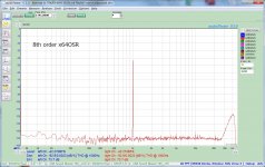
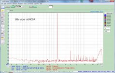
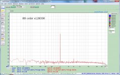
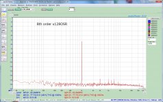
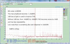
I did measurement of THD from -40dBFS to -60dBFS. I know that such amplitude in 1bitDSM has relatively poor numbers than 0dBFS. It locates at the 2nd or 3rd position in my to-do list, not the 1st one because the problem exists in the digital domain, which isn't fatal to revise a PCB. The top priority is an analog problem like oscillation, which must be fixed before designing a new PCB.
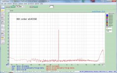
Attached pics are after temporary compensation. 1dB loss of the max gain luckily got a good result with moderate repeatability. Pic.1 to pic.4 is 128OSR. Pic.5 to pic.8 is 64OSR.
Attached pics are after temporary compensation. 1dB loss of the max gain luckily got a good result with moderate repeatability. Pic.1 to pic.4 is 128OSR. Pic.5 to pic.8 is 64OSR.
Attachments


Btw, with your fpga: isn't it really easy to program some form of rtz encoding as well as have the pll generate the necessary clocks for that?
DSM topology (mine is 8th order CRFB with local feedback)in the digital domain and analog FIR in the analog domain must shake hands tightly for better performance. From such a viewpoint, I don't use external modulators like Rpi or windows PC. Pinpoint tweaking between them is mandatory. PC base modulators are far off from actual 1bitDAC array(analog FIR in my case). FPGA is the glue and absorber between them.
I can't say NRZ encoding or clock generation is easy or not. It strongly depends on your analog section. I'm an old school person who still uses only schematic entry for FPGA design. If you use high-level synthesis, some primitive functions may not be accessible. That's why easiness is relevant to your design circumstance.
I did measurement of THD from -40dBFS to -60dBFS. I know that such amplitude in 1bitDSM has relatively poor numbers than 0dBFS. It locates at the 2nd or 3rd position in my to-do list, not the 1st one because the problem exists in the digital domain, which isn't fatal to revise a PCB. The top priority is an analog problem like oscillation, which must be fixed before designing a new PCB.
Attached pics are after temporary compensation. 1dB loss of the max gain luckily got a good result with moderate repeatability. Pic.1 to pic.4 is 128OSR. Pic.5 to pic.8 is 64OSR.
Dynamic range is good and thd is excellent as well so no worries. I have seen worse with nrz;-)
Attached pics are after temporary compensation. 1
What ADC are you using to capture the output from your PCB? - I'm really amazed that you can get these results without Notch filter of some kind...
Maybe without a Notch your also looking at products from the ADC...
Last edited:
- Home
- Source & Line
- Digital Line Level
- My no DAC project, FPGA and transistors