Okay, but you're talking about VREF then, which will be fed by the Jung/Didden Super Regulator, not by the LT3045/LT3094 LDOs directly. So, how would the DAC output bias be affected by the LDOs with respect to PSRR?
Adding the synoptic again for references purposes.
That was an example, not the only possible one.
It could refer to a discrete output stage, too. In some cases even opamps don't sound so good with LDOs.
It might even pass through the Jung regulator to some extent, don't know until I listen and compare it to the linear +15v version.
That was an example, not the only possible one.
It could refer to a discrete output stage, too. In some cases even opamps don't sound so good with LDOs.
It might even pass through the Jung regulator to some extent, don't know until I listen and compare it to the linear +15v version.
Oh sure, but then again, I have some constraints that I cannot escape:
- my power source is USB (whether I like it or not).
- the DAC brick can't be larger than 4.5" × 1.5", and ideally 3" × 1.5".
And with these constraints, I have to live with the fact that my power source is switched, and that I do not have a lot of room to put things like transformers. But as you wrote, with enough time and efforts, there should be a way to make it work, and I make it my goal to find it, one way or another.
These constraints are really important for me. Without any constraints, there can't be any creativity.
Last edited:
Improvement to Power Supply Architecture
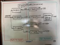
Here is a new refinement of the power supply architecture.
This time, the +15 V line that we need for VREF is totally decoupled from the rest of the power supply system, with a dedicated LTM8045. Doing so, it should reduce the temperature of the regulator, and avoid some level of cross-feeding. With that change, the architecture feels really balanced. Overkill maybe, but balanced.
Also, the more I am reading the documentation for the LTM8045 and LTM8049, the safer the µModule form factor makes me feel (Chris had a great point there). In order to better understand this, one might look at this manual for the DC2244A evaluation board of the LMT8049. Figure 7 on page 6 shows the Radiated EMI CISPR25- Class 5 Peak Limit, which is never crossed, no matter which frequency is being used. If we ever try to get the DAC brick certified, this would certainly help.
Note: This sheet analyzes all the regulators we are planning to use for this power supply system (both boards).
Attachments
Last edited:
Rupert Neve (one of my all-time heroes) just released a new DAC powered by an AKM chip...
POWERING
Operating Mains Voltage: 100-240VAC, 50/60 Hz
AC Power Consumption: 45W Max
Without any constraints, there can't be any creativity.
Any particular constraint on sound quality, or okay if you could have gotten better sound quality from AK4497?
Any particular constraint on sound quality, or okay if you could have gotten better sound quality from AK4497?
Ah! That is a great question.
Yes, I want it to sound as good as possible within the set of self-imposed constraints, and if it were to sound better with AK4497, I would downgrade to that chip. But someone will have to build an AK4497-powered DAC brick with the same constraints while I work on the AK4499 version, because I remain convinced that we can make it sound better.
USB C should be fine. Just ship a powered USB C hub with it that uses wall power.
I just deleted the part of my previous post that wrote about USB-C, because I realized that USB-C gives us up to 3A at 5V, which is massive already (Cf. Wikipedia). For the type of applications that we have, we probably do not need more than that, and there is no point making the system more complex than it already is.
Going with Linear
Unless there is any major objection, I'll go with this list of regulators for a first set of prototype power supplies, because they're all made by Linear, and they're perfectly matched with each other. Also, in my opinion, Linear produces the very best documentations and evaluation boards, with highly detailed explanations of the PCB layout, super cool Jedi tricks like Kelvin connections, and affordable evaluation boards for all their components (at least all the ones that I care about).
Unless there is any major objection, I'll go with this list of regulators for a first set of prototype power supplies, because they're all made by Linear, and they're perfectly matched with each other. Also, in my opinion, Linear produces the very best documentations and evaluation boards, with highly detailed explanations of the PCB layout, super cool Jedi tricks like Kelvin connections, and affordable evaluation boards for all their components (at least all the ones that I care about).
Streamlined 3V3 Line
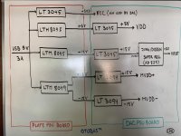
Here is a small change to the power supply architecture that streamlines the +3.3 V line. Clearly, there is no point going from 5 V to 6 V then back down to 3.3 V. Instead, we're better off going straight from 5 V down to 3.3 V. Somehow, I missed that when I made the architecture more balanced in the previous revision...
Also, the OTOBUS™ has been revised in order to provide both ±18V (for MVDD) and 18V (for MVREF). With this latest change, we have as many GND pins as we have non-ground power pins (5 of each).
Attachments
Last edited:

.....meanwhile back in Kansas.
Welcome to the thread Jam! So glad to have you here...
When I grow up, I want to be an analog designer like you...
Unfortunately, there is very little chance that I'll ever grow up.
Oh well...
Component Designators
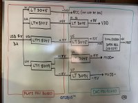
I fixed a typo for U6 on the DAC PSU Board. It's an LT3045, not an LT3094... Also, the component designators are used in reference to this new sheet, where we will analyze the load requirements for each part of the circuit. This will help us ensure that the components we have selected are suitable, and that we won't have too many problems with heat dissipation.
I fixed a typo for U6 on the DAC PSU Board. It's an LT3045, not an LT3094... Also, the component designators are used in reference to this new sheet, where we will analyze the load requirements for each part of the circuit. This will help us ensure that the components we have selected are suitable, and that we won't have too many problems with heat dissipation.
Attachments
Power Supply Requirements
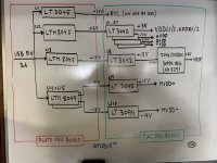
Here is a first analysis of our power supply requirements for the DAC brick. I decided to play it safe, therefore I have dedicated one regulator for each of the following supplies:
- VDDL1
- VDDL2
- VDDR1
- VDDR2
- AVDD
- DVDD
- TVDD
This brings the total number of regulators on the DAC PSU board to 10. That being said, some regulators might move onto the DAC board itself in order to get closer to whatever they need to feed (but it's too early to tell whether this is possible or not, because we also have to fit a lot of capacitors there).
Most of the data populated on the "Requirement" column of the spreadsheet comes straight out of the AK4499 datasheet. But there is one thing that I'm really not sure about: how to evaluate current requirements for the four OPA1612 operational amplifiers used for the audio outputs. There, I played it safe and used the short circuit currents for the OPA1612, which are +55mA and -62mA. This meant that the U9 LT3045 needs 220mA, while the U10 LT3094 needs 248mA.
Unfortunately, if that is the case, it means that we need two LTM8049 regulators on the plate PSU board, because each regulator can only handle 400mA. And I am not even sure that two of these μModules can be mounted in parallel in order to increase current output and reduce noise, like is the case with the LT3045 or LT3094.
Other than that, things seem to be okay, and we're able to move from the 500mA LT3045 down to the 200mA LT3042 for seven regulators on the DAC PSU board, which is great.
Bottomline: we need to find a way to use the LTM8049 in parallel, or we'll have to add four more power circuits to the OTOBUS™ (+18V, -18V and two GND circuits), which means that we would lose either the I²S or the SAI interface. If possible, I would really like to avoid that...
Or maybe we do not need so much power on the output stage...
Thoughts?
Attachments
Last edited:
Bottomline: we need to find a way to use the LTM8049 in parallel, or we'll have to add four more power circuits to the OTOBUS™ (+18V, -18V and two GND circuits), which means that we would lose either the I²S or the SAI interface. If possible, I would really like to avoid that...
I think I found an acceptable solution to that problem: the OTOBUS™ is mirrored through the two sets of ERF8/ERM8 connectors that go from the plate to the brick. Therefore, we could have one set feeding ±18V from one LTM8049, and another set feeding ±18V from a second LTM8049. From there, two of the OPA1612 would feed from one set, and the other two would feed from the other set. Of course, doing that would make us lose the redundancy that our two mirrored OTOBUS™ interfaces give us with respect to the ±18V supply, but this is probably better than maxing out a regulator. And this will keep the amount of current flowing on any ERF8/ERM8 pin under 250mA, which is probably a good thing.
Note: The BOM for all these regulators is now at a respectable $91.31, but this is pretty much in line with the AK4499EQ DAC chip, which costs a cool $77.22... What that tells us though is that some plate might not come with the fancy pair of LTM8049 for every socket, because that would make the cost of a plate go through the roof, and these components won't be used in most instances. In fact, it makes me wonder whether we will want to mount them on standalone PCBs...
Last edited:
I think I found an acceptable solution to that problem...
There is an even better solution: the DAC brick is a multi-unit brick (two at least, possibly three if all the components don't fit within two). Therefore, it will have access to 2 pairs of ERF8/ERM8 connectors, not just one. As a result, while signals should be fetched from a single pair (or the MCU will be totally confused), power supplies could be fetched from both. And that means that we can keep our sets perfectly mirrored, hence fully redundant.
I like that...
Also, total current is modeled to be 672mA, but that does not include the 10mA that go to every pin of the AK4499EQ other than VREF and supplies. It also assumes that our regulators (including the Jung/Didden Super Regulators) have a 100% efficiency, which they obviously don't (they're pretty darn efficient though, at the exception of the Super Regulators perhaps). Therefore, I would expect total current to be in the order of 1A, which should be fine for a USB 3.0 port (1.5A).
Last edited:
Thoughts?
Yes.
* Each I/V current output from the dac is 37ma max., and there are a total of 8.
* There are two I/V opamps in each physical OPA1612
* Computer grounds are notoriously electrically noisy. That's why USB boards may be designed with galvanic isolation. Those computer power supply generated ground currents can make a power amp connected to the dac output sound pretty bad. Same risk for other equipment that may be connected to the module system.
May I ask where you got this figure from? I could not find it in the datasheet nor the evaluation board's manual. And which supply is this output derived from?* Each I/V current output from the dac is 37ma max., and there are a total of 8.
Does it mean that I need to multiply my estimates for MVDD+ and MVDD- by two? That would bring the I/V stage to close to 1A. Is that realistic?* There are two I/V opamps in each physical OPA1612
Indeed, but one could also get USB power from a battery.* Computer grounds are notoriously electrically noisy. That's why USB boards may be designed with galvanic isolation. Those computer power supply generated ground currents can make a power amp connected to the dac output sound pretty bad. Same risk for other equipment that may be connected to the module system.
USB as source of power is an essential part of the modular design. This is not something that we can change unfortunately.
Does it mean that I need to multiply my estimates for MVDD+ and MVDD- by two? That would bring the I/V stage to close to 1A.
USB as source of power is an essential part of the modular design. This is not something that we can change unfortunately.
It is suggested for the designer to read AK4499 data sheet carefully until fully understood.
Also, who says USB power can't be used cleanly? I didn't. I only mentioned an issue for the power supply designer to anticipate and design for as needed.
By the way, for setting up an eval board for test, the idea would be to get it working as well as one possibly can and use that as a reference point to gauge against. In order to manage power grounds for that reference point, there is nothing I have found that is so useful as: Monster HPTS 7000 MkII (and MkII only): https://www.ebay.com/sch/i.html?_from=R40&_trksid=m570.l1313&_nkw=monster+htps7000+mkii&_sacat=0
... as can be seen, unfortunately no MkII models right now. (Easy to see the external difference, the MkII models have different colored LEDs.) Keep and eye out though and grab one when you can. Consider it a necessary piece of test equipment for high end audio.
Last edited:
- Status
- This old topic is closed. If you want to reopen this topic, contact a moderator using the "Report Post" button.
- Home
- Source & Line
- Digital Line Level
- 8 × AK5578EN + 8 × AK4499EQ ADC/DAC Boards