...buttons are needed for manually triggering repetitive actions, like playing a sound...
You might check out the buttons on MIDI beat box control surfaces at a local music store. Guitar Center in Sunnyvale has floor inventory of such things. The point is that one must be able to tap out a groove on a button used to play a sound, and to work well for that it must be possible to tap it very quickly with little movement, yet without any false triggering. Tactile switches may or may not be suitable depending on the particular switch characteristics.
You might check out the buttons on MIDI beat box control surfaces at a local music store. Guitar Center in Sunnyvale has floor inventory of such things. The point is that one must be able to tap out a groove on a button used to play a sound, and to work well for that it must be possible to tap it very quickly with little movement, yet without any false triggering. Tactile switches may or may not be suitable depending on the particular switch characteristics.
Indeed, but the buttons I am talking about won't be used for that. Instead, what you are describing will be handled through pads, like the ones found on many MIDI control surfaces. That being said, I have not focused on bricks for these yet, for two main reasons: first, for the life of me, I could not find the right components for them, mostly because I must be doing my searches with the wrong keywords (pointers much appreciated); second, because I am planning to use a LinnStrument 128 on my reference setup (it provides 128 of these pads and comes with some awesome open source software; and Roger Linn is one of my heroes).
You might check out the buttons on MIDI beat box control surfaces at a local music store. Guitar Center in Sunnyvale has floor inventory of such things. The point is that one must be able to tap out a groove on a button used to play a sound, and to work well for that it must be possible to tap it very quickly with little movement, yet without any false triggering. Tactile switches may or may not be suitable depending on the particular switch characteristics.
Mark,
It's really great to have you follow the thread so carefully, especially with long posts like the one you've just responded to. I appreciate that very much. Thank you!
More Bricks
Here is the follow-on post describing our remaining bricks.
S1, S2, S4: One, Two, or Four Switches
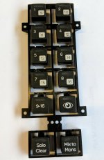
Unlike buttons, switches have a click/detent. Other than that, everything is pretty much the same, at the exception of the button's cap, which needs to support screen printing. And much like with buttons, the challenge for switches will consist in finding the right part. Of all the switches that I have used, the ones that I like the most are those used for the Pro Tools|S3 control surface (see attached picture). I really like their tactile feedback, as well as the way the illumination is handled through a thin horizontal window above the cap's label. I am still trying to find a matching OEM component in the form of a single button (not using a multi-button overlay like the S3 does).
Our instruments need three bricks with switches:
- 1 square switch
- 2 rectangle switches (one on above the other)
- 4 square switches (in a 2 × 2 matrix)
W1: One Wheel
What we call "wheel" is nothing more than a rotary encoder with an oversized knob like the one shown at the top of this module. Ideally, this brick will be the same as the E1 single encoder with LED ring brick, just using a larger knob. Alternatively, we will build it as a single-encoder brick without LED ring, taking into account the fact that it might always be used in conjunction with a display of some kind.
This brick should not be confused with a future wheel "block", which will provide a much bigger wheel with more control actions (back, forward, up, down, select). The wheel in question will be similar to the kind of wheel you find on luxury cards from brands like BMW or Mercedes. Unfortunately, these types of wheel usually come in the form or large OEM components with bulky enclosures that are not suitable to our application (suggestions welcome).
This is it for the bricks offering a single kind of control. Now, let's take a look at the composite bricks:
B2P2: Two Buttons and Two Ports
This brick will have two buttons above two ports. Here, it is worth mentioning that unlike blocks, bricks cannot be rotated. This is due to the fact that the mikroBUS form factor requires 16 different pins across two sets of 8 headers. Therefore, the layout of our non-symmetrical composite bricks needs to be considered carefully. In this particular case, the reason for putting the buttons above the ports is that most Eurorack modules do that, relying on gravity to pull the cables down away from the buttons when the modules are mounted vertically or at an angle.
B2S2: Two Buttons and Two Switches
This brick probably won't be used very often, but is required by one of our instruments. Here, the fact that buttons have round caps while switches have square caps will be quite helpful. The buttons will be on the left and the switches on the right, but I have yet to find a solid justification for this particular layout.
D1B2: One Small Display and Two Buttons
This brick will have a small OLED display (like the one used for the OLED W Click) mounted above two buttons. This particular assembly won't be very common, but this module could really take advantage of it. Down the road, we will also upgrade to a high-resolution display, as planned for the D1 brick. Here, the layout is justified by the fact that putting the buttons above the display would potentially hide the display when a button is pressed, while putting them on the left or right side would require that we mount the display vertically, making it very difficult to display any kind of text.
D1E2: One Small Display and Two Small Encoders
This brick will use the same display as the D1B2 brick, and the same encoders as the small encoders used for the E3 brick. It will be quite useful, being used by 9 of our 23 instruments. The only drawback is that the encoders will be quite small, but we will try to mitigate that problem by mounting them on a separate PCB alongside the screen, therefore allowing them to overlap the pin headers located on the PCB underneath.
D1P2: One Small Display and Two Audio/CV Ports
This brick will be one of the most complex bricks that we have to develop, because it will combine an OLED display and the two ports offered by the P2 brick described in my previous post. Depending on the complexity of the P2 brick, it is possible that we need to use three PCBs instead of two. If that is the case, we will need to plan all other bricks accordingly. That being said, such a requirement might arise for future bricks, especially the ones responsible for producing analog audio outputs (audio oscillators for analog sound synthesis). Bottomline: we will create working prototypes for all bricks before we settle on a definitive mechanical design. Furthermore, we might decide that different bricks could come in different heights (the control surface does not have to be flat in its entirety, and some blocks might be taller than others when a subset of the blocks come with an optional Sitara DSP base).
D1S2: One Small Display and Two Switches
This is the last display brick that we have to build, and it is quite similar to the D1B2 brick, but with two switches instead of two buttons. This particular assembly will be very useful for implementing selectors, like the one offered by this module. And so far, we have not found any need for a D1B1S1 brick made of a small display, a single button, and a single switch, but the need might arise in the future. And so far, 11 or our 23 planned instruments will have at least one display brick, two will have three of them, and one will even have four. Therefore, these little displays are a lot more useful than we were anticipating originally.
E1B1: One Large Encoder with LED Ring and One Button
This brick will have a single encoder with LED ring similar to the E1 brick, plus a small button at the top right corner. This is an unusual arrangement, but it will be very useful for this module. It will certainly be a really tight fit, but we'll give it a shot, and we'll keep this requirement in mind when developing the E1 brick.
E1P2: One Medium Encoder and Two Audio/CV Ports
This brick will combine a medium encoder with two Audio/CV ports. Because of space constraints, the encoder will not come with a LED ring. As a result, this brick should be used in combination with a display brick, or in close proximity to a smartphone. So far, we are planning to use it for a single instrument, which means that we might end up getting rid of it if we find a suitable alternative arrangement.
E2P2: Two Small Encoders and Two Audio/CV Ports
This brick will be similar to the E1P2, but will have two small encoders instead of one medium encoder. It is used extensively by two modules that both make use a display bricks as well. Therefore, it should be quite useful.
E1S1: One Large Encoder with LED Ring and One Switch
This last brick will be similar to the E1B1, but with a switch instead of a button. Because the switch will have a square cap, it will be an even tighter fit than the E1B1, but we like a good challenge, don't we?
That's all for now...
Here is the follow-on post describing our remaining bricks.
S1, S2, S4: One, Two, or Four Switches
Unlike buttons, switches have a click/detent. Other than that, everything is pretty much the same, at the exception of the button's cap, which needs to support screen printing. And much like with buttons, the challenge for switches will consist in finding the right part. Of all the switches that I have used, the ones that I like the most are those used for the Pro Tools|S3 control surface (see attached picture). I really like their tactile feedback, as well as the way the illumination is handled through a thin horizontal window above the cap's label. I am still trying to find a matching OEM component in the form of a single button (not using a multi-button overlay like the S3 does).
Our instruments need three bricks with switches:
- 1 square switch
- 2 rectangle switches (one on above the other)
- 4 square switches (in a 2 × 2 matrix)
W1: One Wheel
What we call "wheel" is nothing more than a rotary encoder with an oversized knob like the one shown at the top of this module. Ideally, this brick will be the same as the E1 single encoder with LED ring brick, just using a larger knob. Alternatively, we will build it as a single-encoder brick without LED ring, taking into account the fact that it might always be used in conjunction with a display of some kind.
This brick should not be confused with a future wheel "block", which will provide a much bigger wheel with more control actions (back, forward, up, down, select). The wheel in question will be similar to the kind of wheel you find on luxury cards from brands like BMW or Mercedes. Unfortunately, these types of wheel usually come in the form or large OEM components with bulky enclosures that are not suitable to our application (suggestions welcome).
This is it for the bricks offering a single kind of control. Now, let's take a look at the composite bricks:
B2P2: Two Buttons and Two Ports
This brick will have two buttons above two ports. Here, it is worth mentioning that unlike blocks, bricks cannot be rotated. This is due to the fact that the mikroBUS form factor requires 16 different pins across two sets of 8 headers. Therefore, the layout of our non-symmetrical composite bricks needs to be considered carefully. In this particular case, the reason for putting the buttons above the ports is that most Eurorack modules do that, relying on gravity to pull the cables down away from the buttons when the modules are mounted vertically or at an angle.
B2S2: Two Buttons and Two Switches
This brick probably won't be used very often, but is required by one of our instruments. Here, the fact that buttons have round caps while switches have square caps will be quite helpful. The buttons will be on the left and the switches on the right, but I have yet to find a solid justification for this particular layout.
D1B2: One Small Display and Two Buttons
This brick will have a small OLED display (like the one used for the OLED W Click) mounted above two buttons. This particular assembly won't be very common, but this module could really take advantage of it. Down the road, we will also upgrade to a high-resolution display, as planned for the D1 brick. Here, the layout is justified by the fact that putting the buttons above the display would potentially hide the display when a button is pressed, while putting them on the left or right side would require that we mount the display vertically, making it very difficult to display any kind of text.
D1E2: One Small Display and Two Small Encoders
This brick will use the same display as the D1B2 brick, and the same encoders as the small encoders used for the E3 brick. It will be quite useful, being used by 9 of our 23 instruments. The only drawback is that the encoders will be quite small, but we will try to mitigate that problem by mounting them on a separate PCB alongside the screen, therefore allowing them to overlap the pin headers located on the PCB underneath.
D1P2: One Small Display and Two Audio/CV Ports
This brick will be one of the most complex bricks that we have to develop, because it will combine an OLED display and the two ports offered by the P2 brick described in my previous post. Depending on the complexity of the P2 brick, it is possible that we need to use three PCBs instead of two. If that is the case, we will need to plan all other bricks accordingly. That being said, such a requirement might arise for future bricks, especially the ones responsible for producing analog audio outputs (audio oscillators for analog sound synthesis). Bottomline: we will create working prototypes for all bricks before we settle on a definitive mechanical design. Furthermore, we might decide that different bricks could come in different heights (the control surface does not have to be flat in its entirety, and some blocks might be taller than others when a subset of the blocks come with an optional Sitara DSP base).
D1S2: One Small Display and Two Switches
This is the last display brick that we have to build, and it is quite similar to the D1B2 brick, but with two switches instead of two buttons. This particular assembly will be very useful for implementing selectors, like the one offered by this module. And so far, we have not found any need for a D1B1S1 brick made of a small display, a single button, and a single switch, but the need might arise in the future. And so far, 11 or our 23 planned instruments will have at least one display brick, two will have three of them, and one will even have four. Therefore, these little displays are a lot more useful than we were anticipating originally.
E1B1: One Large Encoder with LED Ring and One Button
This brick will have a single encoder with LED ring similar to the E1 brick, plus a small button at the top right corner. This is an unusual arrangement, but it will be very useful for this module. It will certainly be a really tight fit, but we'll give it a shot, and we'll keep this requirement in mind when developing the E1 brick.
E1P2: One Medium Encoder and Two Audio/CV Ports
This brick will combine a medium encoder with two Audio/CV ports. Because of space constraints, the encoder will not come with a LED ring. As a result, this brick should be used in combination with a display brick, or in close proximity to a smartphone. So far, we are planning to use it for a single instrument, which means that we might end up getting rid of it if we find a suitable alternative arrangement.
E2P2: Two Small Encoders and Two Audio/CV Ports
This brick will be similar to the E1P2, but will have two small encoders instead of one medium encoder. It is used extensively by two modules that both make use a display bricks as well. Therefore, it should be quite useful.
E1S1: One Large Encoder with LED Ring and One Switch
This last brick will be similar to the E1B1, but with a switch instead of a button. Because the switch will have a square cap, it will be an even tighter fit than the E1B1, but we like a good challenge, don't we?
That's all for now...
Attachments
Updated Reference Setup
Another unexpected consequence of increasing the size of our blocks to 96mm × 96mm is that we can combine the LinnStrument 200, Apple Magic Keyboard, Apple Magic Trackpad, and 3Dconnexion SpaceMouse across 3 grids on our reference setup, with a perfect fit. Doing so, we're saving a ton of space, allowing us to fit not only all currently-available Mutable Instruments modules, but also the OTO replicas of the five relevant Korg Volca modules (Cf. instruments). And all that was required to make this happen is a new E4 brick containing 4 small encoders, plus a 2-unit brick for the ultra cool Nutube.
Of course, these Korg Volca replicas do not have any built-in keyboard, but that's actually for the best, because they're placed right on top of the 200-pads LinnStrument, and 200 5-dimension pressure-sensitive pads surely beat 16 capacitive keys when trying to play some music...
And to top it off, the other knob next to the channel module will be the Grayhill Touch Encoder, used as master volume control knob (among other programmable functions).
Last edited:
Analog chips for modular synthesis
Over the past couple of years, with some patents expiring, there has been a sort of renaissance for analog chips used for modular synthesis, like the CEM3340 voltage controlled oscillator. I knew about CoolAudio and their V3340 clone, but I had not paid close attention to JSC ALFA, a 60 year old company based in Riga, Latvia. Their line of application specific integrated circuits is really impressive. I will get samples of the following chips to prototype some analog bricks:
- AS2164
- AS3310
- AS3320
- AS3330
- AS3340
- AS3350
- AS3360
- AS3363
- AS3364
- AS3372E
- AS3394E
The list of analog bricks that we will play with is maintained on this sheet.
Last edited:
Development Kit
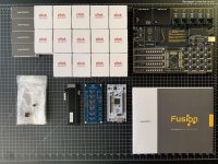
Santa Claus disguised as a FedEx delivery man made a stop at my place this morning...
- MikroE Fusion development board
- 18 Click Boards
- NUCLEO-H743ZI2
- Silicon Labs Digital Isolators
- Bourns PSP Motorized Fader
- Various Controls and Hirose Connectors
I am happy to report that the MikroE Fusion is absolutely first class. The quality of the construction is amazing. The whole thing is essentially a massive 3.25mm thick PCB. It feels really, really good, and it makes me want to build our USB grid using the same process. Also, the MCU card is 61mm × 61mm, which is perfect for what we need. Now, we just need to get the right MCU for the Thesycon U-Hear firmware, or build our own.
Time to play with all that stuff...
Attachments
Last edited:
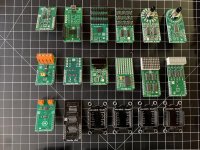
Click Boards
Here are the 18 Click Boards that we got. They are really, really well made.
And I was not sure whether they came with soldered headers or not. They do.
Having bricks in that form factor will be really awesome, not just for controls, but also for analog ICs. Being able to put together a complete analog synthesizer with vintage ICs using 9 bricks on a single OTO plate would be awesome. And combining 6 of these on a board (new name for "grid") should be a ton of fun...
Attachments
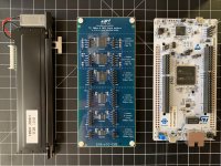
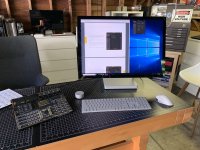
Mikroe Fusion v8 Up and Running
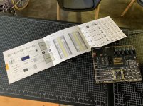
My Mikroe Fusion v8 development board is up and running. Since I have been using Macs for the past 20 years but did not want to take any chance with a virtual machine, I got a new PC running Windows 10. Now I need a compiler for the MCU, and I'll probably go for mikroC PRO, just to keep things simple. The large schematic printed on thick waterproof card stock is a really nice touch by the way... Mikroe originally started as a magazine and book publisher, and it shows: these folks know how to produce really good documentation for their products.
My Mikroe Fusion v8 development board is up and running. Since I have been using Macs for the past 20 years but did not want to take any chance with a virtual machine, I got a new PC running Windows 10. Now I need a compiler for the MCU, and I'll probably go for mikroC PRO, just to keep things simple. The large schematic printed on thick waterproof card stock is a really nice touch by the way... Mikroe originally started as a magazine and book publisher, and it shows: these folks know how to produce really good documentation for their products.
Attachments
I've never used their IDE or compilers. For ARM MCUs I have used Keil many times in the past, they were purchased by ARM a few years ago. It's not cheap, so for a self-funded project I would look at using the STM32CubeIDE, which I think is Atollic TrueStudio that ST Micro purchased and made free for STM32.
I'm not saying the Mikroe stuff is bad at all, but I've never used it or know of anyone that has.
I'm not saying the Mikroe stuff is bad at all, but I've never used it or know of anyone that has.
Last edited:
I've never used their IDE or compilers. For ARM MCUs I have used Keil many times in the past, they were purchased by ARM a few years ago. It's not cheap, so for a self-funded project I would look at using the STM32CubeIDE, which I think is Atollic TrueStudio that ST Micro purchased and made free for STM32.
I'm not saying the Mikroe stuff is bad at all, but I've never used it or know of anyone that has.
Great advice! I'm probably going to try a few before I find one that I like...
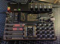
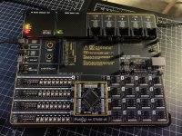
Blinking LEDs
LEDs are blinking, as they should.
The mikroC PRO IDE is a fairly conventional Eclipse-based IDE. A bit dated from a UI standpoint, but perfectly functional. The CODEGRIP Suite used to write on the MCU seems a bit flaky, but this might be due to user errors...
LEDs are blinking, as they should.
The mikroC PRO IDE is a fairly conventional Eclipse-based IDE. A bit dated from a UI standpoint, but perfectly functional. The CODEGRIP Suite used to write on the MCU seems a bit flaky, but this might be due to user errors...
Attachments
We just heard back from Thesycon regarding the U-Hear firmware. We're not under any NDA with them, but I won't disclose their pricing out of courtesy. That being said, I am pleased to report that we should be able to afford it, and that the contribution to our BoM for the AK4499EQ-powered DAC block should be less than 10%. Also, they do support the STM32F723 alongside the STM32H743, which makes me hopeful that they could support the STM32F767ZG currently offered by MikroE as an MCU Card. If that were to be the case, it would accelerate our development efforts quite significantly.
As far as I can tell, an evaluation is already available, but I am waiting for some confirmation.
I am super excited about this... So much better than the XMOS alternative (on paper at least)...
Glad its looking good with Thesycon
") Please keep us updated - if it works well at the end of the day then it might encourage us to jump the XMOS ship - there would be no sad faces around here...
Please keep us updated - if it works well at the end of the day then it might encourage us to jump the XMOS ship - there would be no sad faces around here...Just got notification from DHL that our bare PCB's from China with our latest designs using XMOS are on the way - expected arrival on the 5th...
BTW. We use JLCPCB for very VERY good small Qty PCB pricing and service (so far - I hope I've not just cursed the quality of the PCB's on there way to us) - we have spun maybe 50 different boards with them now, not a single issue or duff board!!!
Your going a bit nuts with the number of PCB layers etc. - I've never designed a PCB with more then 4 layers...
PCB Prototype & PCB Fabrication Manufacturer - JLCPCB
A division of JLC PCB have started to sell components - some are good pricing, especially items like connectors that are stupid cost outside of China.
Electronic Components Distributor | EasyEDA Parts Online Store - LCSC
JLCPCB also offer Framed SMD solder paste stencil for like US$16!!!
(I have no affiliation with JLCPCB, but there low cost and decent quality has completely changed our development costs). The PCB's typically arrive within 7 days to no later then 10 days from order for multi-layer boards with solder paste stencil...
Last edited:
Glad its looking good with Thesycon
Just got notification from DHL that our bare PCB's from China with our latest designs using XMOS are on the way - expected arrival on the 5th...
BTW. We use JLCPCB for very VERY good small Qty PCB pricing and service (so far - I hope I've not just cursed the quality of the PCB's on there way to us) - we have spun maybe 50 different boards with them now, not a single issue or duff board!!!
Your going a bit nuts with the number of PCB layers etc. - I've never designed a PCB with more then 4 layers...
PCB Prototype & PCB Fabrication Manufacturer - JLCPCB
A division of JLC PCB have started to sell components - some are good pricing, especially items like connectors that are stupid cost outside of China.
Electronic Components Distributor | EasyEDA Parts Online Store - LCSC
JLCPCB also offer Framed SMD solder paste stencil for like US$16!!!
(I have no affiliation with JLCPCB, but there low cost and decent quality has completely changed our development costs). The PCB's typically arrive within 7 days to no later then 10 days from order for multi-layer boards with solder paste stencil...
I've used JLC, they are great for simple prototypes. Their FR4 is low grade low Tg though. That aside, it is impossible to beat their specs for the cost if you can accept the limitations of the standard panel.
There is no need to limit yourself to 4 layers when the BOM cost is going to be as high as this. Spending time to squeeze a design into 4 layers is fine if you are mass producing it. There are lots of designs that require more than 4 layers. Anything of high component density or with large / fine pitch BGAs practically requires it. It also can involve EMC or power distribution compromises. If you end up having to pay the NRE for HDI techniques you might find the cost barely changes if you add layers.
If you are doing it for a commercial product range, I would have considered designing my own USB Audio Class 2.0 receiver in an FPGA with a MicroBlaze / NIOS soft processor to adapt existing examples from other architectures. I am pretty sure you will not get channel counts like 8 in 8 out with an STM32, not at the 384 kHz+ rates anyway. The driver used to be a concern, but now that Windows 10 has a UAC2 compliant driver, I'd venture to guess most people buying expensive USB DACs are running Windows 10 if they are running Windows at all. Guess it depends on volume if that makes sense.
Last edited:
WRT FR4 Tg I only use leaded solder in the lab, and no plans to change - I don't think JLC PCB's are any worst then what we use for MP. I've never had tracks lift during rework / development on the bench, and that's a good sign - I've had many worst experiences with track lifting from cheaper suppliers in China
We have inhouse implentations of USB2.0 audio for ARM CPU's - Sadly we need to support legacy OS so the UAC2 driver for Windows is essential. There are also limitations with the windows 10 UAC2 driver (IIRC limitations with DSD and Higher Res ADC support) - Also the "Expanded" Thesycon driver supports firmware upgrade bootloaders etc.
We where one of the first to implement MQA, which in the early days was targeted more to XMOS solutions - its different now, but we have so much hard earn experience with our customized XMOS MQA code that we rather play safe... One day we will be brave... but we have too many designs on the go to risk issue porting to a new platform ATM.
While working with XMOS is fraught with despair and frustration, we now have it where it "Can Work" - but only due to pure sweat and blood... I'd not recommended it to anyone (well unless I really REALLY hated them, and indeed I could never be that cruel...)!
Last edited:
Glad its looking good with Thesycon
Just got notification from DHL that our bare PCB's from China with our latest designs using XMOS are on the way - expected arrival on the 5th...
BTW. We use JLCPCB for very VERY good small Qty PCB pricing and service (so far - I hope I've not just cursed the quality of the PCB's on there way to us) - we have spun maybe 50 different boards with them now, not a single issue or duff board!!!
Your going a bit nuts with the number of PCB layers etc. - I've never designed a PCB with more then 4 layers...
PCB Prototype & PCB Fabrication Manufacturer - JLCPCB
A division of JLC PCB have started to sell components - some are good pricing, especially items like connectors that are stupid cost outside of China.
Electronic Components Distributor | EasyEDA Parts Online Store - LCSC
JLCPCB also offer Framed SMD solder paste stencil for like US$16!!!
(I have no affiliation with JLCPCB, but there low cost and decent quality has completely changed our development costs). The PCB's typically arrive within 7 days to no later then 10 days from order for multi-layer boards with solder paste stencil...
Yes indeed, I am very encouraged by what could be done with Thesycon. They are not the most responsive, but this is to be expected from a tiny European company in the middle of the Summer. Also, I just heard back from MikroE, and there is good hope that we could get an MCU Card with the STM32H743, which is one of the two chips supported by the Thesycon driver, and the best one that ST has to offer for what we need (we do not need the 753 version with encryption).
As far as the PCB is concerned, we still have a lot of work ahead of us before we can determine the final number of layers. If we could stick to 4, we will, because it would make the design a lot simpler, and it would allow us to work with suppliers like JLCPCB (thanks a lot for the recommendation btw). They also support 6 layers, so we'll study that configuration in more details.
The reason why I am saying that things will take a bit of time is that I am currently trying to decide which CAD tool to use. On a Mac, I was limited to Eagle and KiCad. Eagle is highly frustrating (to me), and I have pretty much given up on it. KiCad is clearly better and is improving fast, but it's not as integrated and polished as I would like it to be. Ultimately, I want to use Altium Designer, because this is what many of the companies I am working with for other projects are using, but it's quite expensive. Therefore, I am considering starting with Altium CircuitStudio. The problem is that every time I change my EDA tool, I have to learn the new tool and redesign a lot of the libraries, so it's slowing me down a bit, but I view that as a good investment, because if we go down the path of building all the bricks that we are dreaming about, we will need solid foundations on that front.
I've used JLC, they are great for simple prototypes. Their FR4 is low grade low Tg though. That aside, it is impossible to beat their specs for the cost if you can accept the limitations of the standard panel.
There is no need to limit yourself to 4 layers when the BOM cost is going to be as high as this. Spending time to squeeze a design into 4 layers is fine if you are mass producing it. There are lots of designs that require more than 4 layers. Anything of high component density or with large / fine pitch BGAs practically requires it. It also can involve EMC or power distribution compromises. If you end up having to pay the NRE for HDI techniques you might find the cost barely changes if you add layers.
If you are doing it for a commercial product range, I would have considered designing my own USB Audio Class 2.0 receiver in an FPGA with a MicroBlaze / NIOS soft processor to adapt existing examples from other architectures. I am pretty sure you will not get channel counts like 8 in 8 out with an STM32, not at the 384 kHz+ rates anyway. The driver used to be a concern, but now that Windows 10 has a UAC2 compliant driver, I'd venture to guess most people buying expensive USB DACs are running Windows 10 if they are running Windows at all. Guess it depends on volume if that makes sense.
Yes, going with an FPGA would probably be best, but it would increase the complexity of the effort by an order of magnitude at least. Currently, the DAC block only needs to support 4 outputs, so we should be fine. Also, now that we have this submodular architecture with USB and mikroBUS, having a rich MCU is really helpful. If we were to go with an FPGA, we probably would have to dedicate a lot of the FPGA's programmable logic to some interfaces, or add additional components alongside. In other words, having a powerful-enough MCU like the STM32H743 should allow us to kill two birds with one stone: 1. providing a solid USB Audio interface for the DAC block; 2. providing a rich platform for driving the 9 bricks that can be mounted on a block's plate.
My hope is that running Thesycon U-Hear on the STM32H743 will be relatively straightforward and that we will have a MikroE MCU Card with that chip. If all that happens as I hope it will, it should allow us to focus our efforts on the design of the DAC PCB and the mechanical design of the USB tray (what I used to call a "grid"), USB blocks, and mikroBUS bricks. Because we want something that is very high quality, the mechanical design is probably the hardest part of the project. Fortunately, we know a couple of people who can give us a hand once we have a baseline design in place.
WRT FR4 Tg I only use leaded solder in the lab, and no plans to change - I don't think JLC PCB's are any worst then what we use for MP. I've never had tracks lift during rework / development on the bench, and that's a good sign - I've had many worst experiences with track lifting from cheaper suppliers in China
We have inhouse implentations of USB2.0 audio for ARM CPU's - Sadly we need to support legacy OS so the UAC2 driver for Windows is essential. There are also limitations with the windows 10 UAC2 driver (IIRC limitations with DSD and Higher Res ADC support) - Also the "Expanded" Thesycon driver supports firmware upgrade bootloaders etc.
We where one of the first to implement MQA, which in the early days was targeted more to XMOS solutions - its different now, but we have so much hard earn experience with our customized XMOS MQA code that we rather play safe... One day we will be brave... but we have too many designs on the go to risk issue porting to a new platform ATM.
While working with XMOS is fraught with despair and frustration, we now have it where it "Can Work" - but only due to pure sweat and blood... I'd not recommended it to anyone (well unless I really REALLY hated them, and indeed I could never be that cruel...)!
Well, I will share everything I learn on this thread, the good, the bad, and the ugly. But you'll have to bear with me, as I am a total newbie. Therefore, I will also share things that must seem totally trivial and akin to pure noise. But that's all part of the process I guess...
Audio/CV Port Design
One of the most critical components of our submodular architecture (USB + mikroBUS) in the context of modular audio synthesis is the P4 brick, which is supposed to offer four hybrid AC/CV ports. This brick is used by 20 of the 23 instruments that we are planning to build. This is a challenging brick to design, because each of its four TRS ports will need to carry a wide range of mutually-exclusive signals (on the left channel, the right one being used for the signal's digital signature):
- Audio input (-5V to +5V)
- Audio output (-5V to +5V)
- Control input (-2.5V to +2.5V or 0V to 8V)
- Control output (-2.5V to +2.5V or 0V to 8V)
- Trigger, gate, or clock input (0 to 5V)
- Trigger, gate, or clock output (0 to 5V)
The audio inputs/outputs do not need to be of super high quality, but 24-bit/94kHz with decent SNR would be nice. For four channels, we could use something like the TLV320AIC34. The control inputs/outputs do not need more than 12 bits, therefore something like the AD5593R would be great (even though it would waste 4 of its 8 channels).
What makes the design difficult is that we want any port to be either an input or an output, for audio or for control, on demand. This is particularly challenging because audio and control ports require different voltage ranges, while Eurorack is not backed by a solid specification. As a result, different vendors of Eurorack modules implement the standard in different ways, which prompted the writing of this kind of alternative specification (which does not seem to be gaining much traction).
Ideally, we could do everything with a single chip, using an audio chip like the TLV320AIC34 to handle both audio and control ports, but I am not sure how to address the issue of different voltage ranges. And we will want to make sure that our ports are well-enough protected to support patching from external Eurorack modules that might have taken the original specification a bit too liberally.
Bottomline: we are still not sure what to do there...
Last edited:
Question about audio input handling
I have an audio input that needs to be fed to an ADC chip and to an analog filter at the same time. What kind of circuit should be added (if any) in order to preserve the original input level without degrading sound quality too much? This question is related to our hybrid AC/CV ports, not to the HiFi DAC block, therefore sound quality is important, yet not that important...
I have an audio input that needs to be fed to an ADC chip and to an analog filter at the same time. What kind of circuit should be added (if any) in order to preserve the original input level without degrading sound quality too much? This question is related to our hybrid AC/CV ports, not to the HiFi DAC block, therefore sound quality is important, yet not that important...
- Status
- This old topic is closed. If you want to reopen this topic, contact a moderator using the "Report Post" button.
- Home
- Source & Line
- Digital Line Level
- 8 × AK5578EN + 8 × AK4499EQ ADC/DAC Boards