The DB2132000L used for D1..4 is marked as "End of Life" by Mouser. Any recommendation for a suitable alternative?
And how on Earth can a brand-new evaluation board use EoL components? This is beyond me...
AKM does not seem to do a very professional job like AD, TI, Cirrus, etc. Their documentation is relatively poor in comparison. I am sure it has something to do with the size of the company as well. I've noticed they have a strong made-in-Japan preference where you will see them select parts from Japanese vendors unless they absolutely can't. Panasonic makes good parts, but I'm not sure they have the same commitment to lifespan that some of their competitors do.
I don't really understand the point of it, but these are close matches at Digikey:
NXP PMEG3020BEP,115
Toshiba CRS09(TE85L,Q,M)
It's probably there for reverse voltage protection and can be omitted.
Last edited:
Regarding R7...
From AK4499 Data Sheet page 9, pin-105:
EXTR - input - External Resistor connection pin. This pin should be
connected to 33 kΩ (±1 %) to AVSS.
Great catch. I should have thought of reading the chip's datasheet... And I confirm that this is the resistor found on the board. Somehow, I had missed it.
Do you understand the particular symbology used for this resistor on the datasheet (the two sets of two concentric circles)?
And do you understand why all these resistors are mounted so close to the edge of the board near the board-to-board connector? Is it just to get some clearance from the large capacitor in order to facilitate assembly, or is there another (more important) reason for that?
AKM does not seem to do a very professional job like AD, TI, Cirrus, etc. Their documentation is relatively poor in comparison. I am sure it has something to do with the size of the company as well. I've noticed they have a strong made-in-Japan preference where you will see them select parts from Japanese vendors unless they absolutely can't. Panasonic makes good parts, but I'm not sure they have the same commitment to lifespan that some of their competitors do.
I don't really understand the point of it, but these are close matches at Digikey:
NXP PMEG3020BEP,115
Toshiba CRS09(TE85L,Q,M)
It's probably there for reverse voltage protection and can be omitted.
You mentioned that earlier, and the longer I am studying their documentation materials, the more I appreciate your comment. There is a clear preference for domestic components, and some parts of the documentation could have used a bit more love and care...
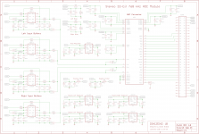
The schematic of page 58 that was made to look like an actual circuit is really, really hard to read (unconventional layout and poor PDF rendering). I am trying to draft a more conventional version that should make it easier to understand how the circuit works, because so far, I am a bit lost...
And thanks a ton for the diode recommendations, this is really helpful.
Do you understand the particular symbology used for this resistor on the datasheet (the two sets of two concentric circles)?
Could simply mean that the value was unknown at the time they finalized the current version of the document.
And do you understand why all these resistors are mounted so close to the edge of the board near the board-to-board connector?
The 10-ohm resistors might be at the edge to make it easier to test adding more caps on the dac chip side of the resistors, also might make it easier to try testing with different value resistors.
R7 might be near the edge to make it easier to add it later in the assembly process. If I were to take a guess, I would say it might be a reference resistor to set the output level of the dac chip so that multi-mono dac chip designs will see the same output level from each dac chip. Otherwise there could be some chip to chip variation in output due to manufacturing tolerances of the internal switched resistor networks.
Could simply mean that the value was unknown at the time they finalized the current version of the document.
The 10-ohm resistors might be at the edge to make it easier to test adding more caps on the dac chip side of the resistors, also might make it easier to try testing with different value resistors.
R7 might be near the edge to make it easier to add it later in the assembly process. If I were to take a guess, I would say it might be a reference resistor to set the output level of the dac chip so that multi-mono dac chip designs will see the same output level from each dac chip. Otherwise there could be some chip to chip variation in output due to manufacturing tolerances of the internal switched resistor networks.
I see. So, if I understand all this correctly, the location of these resistors does not matter much as long as they are on the same board as the DAC chip. If so, I'll prioritize the capacitors, oscillators, and operational amplifiers, probably with this set of priorities:
1. Small capacitors (as close as possible to the DAC's pins)
2. 470μF capacitors (as close to the small capacitors as possible)
3. Operational amplifiers
4. Clock oscillators
5. 10μF capacitors
6. Resistors
Question about shielding
If we shield the DAC chip with a metal frame, should we put the OPA1612 operational amplifiers inside the shield or outside?
And if we use such a shield, we obviously cannot include the 470μF capacitors. Therefore, for the four that are mounted on the top of the reference board, is it better to keep them on the top but then we have to move them by about 5mm away from the DAC chip, or to move them to the underside of the board, but then we have to add a via (because they are surface mounted).
Resistors
For the resistors, we will go for the Vishay TNPW e3 series. This will give us all the resistor values that we need, at the exception of 5.1Ω, which will be handled by the TE Connectivity CPF0603B5R1E1. The TNPW e3 will be used in 0603 package and will give us:
- 0.1% tolerance
- 0.125W rated dissipation
- 75V operating voltage
- 155 °C permissible temperature
For most of the DAC board, it's probably overkill, but better safe than sorry...
5. 10μF capacitors
Depends what the 10uf caps are there for. If for bypassing, they need to be close.
Also in general, where things go depends not on what they are named or their values exactly. It depends on their electrical function in the circuit. Caps, resistors, opamps, etc., are used for many, many purposes, and one needs to learn to look at a schematic and understand the function of each component, or analyze the circuit to find out. Read, The Art of Electronics, and you will start to see for yourself what I mean.
Despite the fun being in the building of things, at least for some of us, there is a good reason our training starts with books and theory, not building.
Last edited:
Depends what the 10uf caps are there for. If for bypassing, they need to be close.
Also in general, where things go depends not on what they are named or their values exactly. It depends on their electrical function in the circuit. Caps, resistors, opamps, etc., are used for many, many purposes, and one needs to learn to look at a schematic and understand the function of each component, or analyze the circuit to find out. Read, The Art of Electronics, and you will start to see for yourself what I mean.
Of course. I am just writing this in reference to the layout of the reference board. There, the 10µF capacitors are quite far from the DAC chip, and no particular effort was made to bring them any closer.
I will read The Art of Electronics as soon as I am done with Ott's book, but this won't happen overnight, and I don't think I can resist the urge of designing a first layout for the board. While this early work might be wasted, it's really helping me become more familiar with the chip's datasheet and the reference board's layout.
Fortunately, I'll be sitting in planes for most of next week, so I'll have plenty of time to catch up on reading materials...
")
Despite the fun being in the building of things, at least for some of us, there is a good reason our training starts with books and theory, not building.
Please do not get me wrong: I really respect that. And I am aware that I am approaching things in a rather unconventional manner. But when you are on such an accelerated crash course, you need to combine both at the same time, otherwise you quickly become discouraged by the dry theoretical side of things. Doing actual work while reading the books really helps me put things in context. Even if most of it turns out to be junk at the beginning.
Naturally, I am more attracted by the conceptual side of things. For example, I can write this kind of mathematics (if you decide to read it, make sure to read this one first, please). But when I focus on the theoretical side of things, I run the risk of believing that I have understood something, while in fact I have missed the essence of it. By forcing myself to spend time and efforts on the practical side of things, I can develop an intuitive understanding of things. And it's only when the two sides meet that I am starting to understand how the whole thing is supposed to work.
Unfortunately, this makes for a messy learning process (who likes the acrid smell of burned electronics?), but I do not know any other way of doing it when trying to approach a brand new field of knowledge at a super accelerated pace.
Last edited:
Learning from my mistakes
Here is a funny story about my rather unusual learning process.
Fifteen years ago, I got married. The minister at my wedding was a friend and happened to be the guy who designed all the electronics for the first iPod. He then went on to run Apple's mobile electronics group, up until the fifth-generation iPhone, managing about 1,000 engineers. One of the nicest guys you'll ever meet. A common friend of ours was a member of the mechanical design team for the first aluminum Power Mac G4.
At the time, I was interested in learning about aluminum profiles. Not just the profiles themselves, but the entire system that is built around them, especially the fasteners. Item in Germany makes the best components that I know. So I decided to give myself an insane project that would give me the opportunity to learn a lot about this system, while making some kind of tribute to my friends. The idea was to build an iPod on wheels (see pictures). Yes, it was as crazy as it sounds...
The whole thing was made out of aluminum, and when the doors and top panels were closed, you could not see a single fastener from the outside. The Power Mac was mounted on a miniature version of the ball bearings used for the rotating ladder on a fire truck engine. And the doors, themselves mounted on geared aluminum profile hinges and softened with pneumatic pistons, could be unlocked with the same keypad used to protect access to an airliner's cockpit post September 11. A pretty decent integrated amplifier was mounted vertically on the back of the aluminum display, and the loudspeakers themselves were made out of milled aluminum.
The whole thing ended up costing more than an entry-level car, and was over 400 pounds.
From a product design standpoint, it was a total disaster. The whole thing makes absolutely no sense at all. It's ridiculous, bordering on the obscene. But it was one of the best learning experiences I ever put myself through. Why? Because in order to make it work (sort of), I had to learn everything about every single product sold by Item (there are literally thousands of them). I had to develop a really deep understanding of the different fastening techniques, the pros and cons, and when to use them. And I got to do that because I started with an insane set of constraints (like no visible fastening elements).
This monstrosity was nothing more than a science project, but it taught me some really valuable engineering lessons. And it gave me a really good feel for how to work with aluminum.
Yesterday, two friends of mine who started an intelligent vision company called me to ask me which robotic arm they should use in order to move a camera around some objects they need to train their artificial vision system against. Thanks to the experience acquired through this insane project, I told them that a robotic arm was probably not the best way to go about solving their problem. Instead, we used the Item aluminum profiles to design a fixed gantry for a matrix of 9 or 16 GoPro cameras, and the only moving part is a turntable on which the scanned object will rest. Without having gone through the process of working on my silly project, I would never have been able to give them this piece of advice, and they might have gone down the rabbit hole of trying to use a robotic arm (the one they were considering had a meter-long reach and was powerful-enough to kill someone if programmed wrong).
Attachments
-
 2707886977_de2752b8ac_o.jpg614.5 KB · Views: 113
 -
 2708705650_6f1776e2fa_o.jpg527 KB · Views: 117
 -
 2708701988_3e86391e6a_o.jpg746.7 KB · Views: 120
 -
 2708699206_e29f363f63_o.jpg688 KB · Views: 108
 -
 2707894929_e1bc1c30be_o.jpg724.9 KB · Views: 107
 -
 2707891999_1a5aabb70b_o.jpg675.2 KB · Views: 53
 -
 2708708554_3fac801606_o.jpg768.1 KB · Views: 53
Last edited:
...Without having gone through the process of working on my silly project, I would never have been able to give them this piece of advice...
Yes, but a good mechanical engineer should have been able to. The problem is that the founders asked for the wrong type of advice. How would you advise them to fix that 'meta-problem' for the future?
Happy accident
Another by-product of my learning process is that it can create happy accidents. Here is an interesting one:
I started to work on my sound processing system (see first two pictures) four years ago. This first design was supposed to use some FPGAs, but I did not know how to use them, so I focused on the ADC and DAC components first (the schematic is for the ADC module, using an older AKM chip). In order to learn more about FPGAs, I got in touch with a few SoM developers, and I met a really good one in Switzerland. We became friends, and I told him about my dream of eventually building my own computer. He liked the idea, and we designed a new kind of storage-attached compute accelerator together. I specified its main characteristics, and he figured out a proper mechanical design and did all the electronics. In other words, I did about 0.1% of the work, and he did the rest, but my original intuition was the spark that made the whole thing possible in the first place.
The result is a dual-slot PCIe board with 16 of Xilinx's most powerful FPGAs and 64TB of on-board flash. We use the transceivers of the FPGAs to drive the flash in a massively parallel fashion. This allows us to read and write the flash at about 85GB/s, which is faster than the RAM bandwidth on a Xeon server... I wish I could post a picture of it, but I can't.
I really get a kick out of provoking such accidents...
Attachments
Yes, but a good mechanical engineer should have been able to. The problem is that the founders asked for the wrong type of advice. How would you advise them to fix that 'meta-problem' for the future?
Anyone who believes to know the answer to that question could make a ton of money on the speaking circuit my friend...
Anyone who believes to know the answer to that question could make a ton of money on the speaking circuit my friend...
People are learning about it, but doing it is complicated. Business schools are starting to teach it, the US military is integrating some of it into its organizational structure, etc. Sometime later its another area you could study. Start with Kahneman.
People are learning about it, but doing it is complicated. Business schools are starting to teach it, the US military is integrating some of it into its organizational structure, etc. Sometime later its another area you could study. Start with Kahneman.
So funny that you are mentioning that!
Twenty years ago, I had another happy accident. I was fresh off the boat in Silicon Valley, and I started a company doing open source software (the term "open source" had just been coined). One thing leading to another, I got interested in the notion of business processes. Knowing not much about the topic, I coined the term "Business Process Management" and defined how a "Business Process Management System" should work. I then created a non-profit organization called the Business Process Management Initiative that went on to develop the Business Process Modeling Notation (BPMN), which is now used everywhere (I did not author it though, a great guy named Stephen A. White did). After I was done with all that, one of the guys I worked with at the time told me to read about TRIZ. I have yet to follow his advice, because I do not want to approach this meta-subject at a purely theoretical level. Before I dive into it, I want some direct experience from multiple engineering disciplines. Otherwise, I'll make the same meta mistakes that I made with BPMN, which were to focus too much on the solution rather than focusing on the problem. As one said really well:
"Fall in love with the problem, not the solution."
One of my many flaws is that I fall in love with solutions...
Some lessons are harder to learn than others...
And some passions can be difficult to overcome...
But they can also be a powerful driver...
In the end, it's all about striking the right balance...
I'm still working on it...
Cheers!
Last edited:
So funny that you are mentioning that!
Not at all what I am talking about. Kahneman, Tetlock, Stanovitch, Nisbett, Thaler, Haidt, and we probably have to include Cialdini. The list goes on, but its a good start.
Last edited:
Not at all what I am talking about. Kahneman, Tetlock, Stanovitch, Nisbett, Thaler, Haidt, and we probably have to include Cialdini. The list goes on, but its a good start.
Kahneman and TRIZ are often quoted by the same books and papers, so I'm a bit confused. Which book from Kahneman that has nothing to do with TRIZ do you believe I should read then?
Recommend starting with 'Thinking Fast and Slow,' cover to cover. The reference section is important in all the books, sometimes its a third of what was written. Tetlock, 'Superforecasting' is the latest, important to know something about 'Expert Judgement.' Stanovitch can be found by searching for 'disrationality.' Nisbett, 'Mindware,' an offering of tools to assist.
Kahneman is probably quoted because his work applies to many developments, his Nobel Prize was for Judgement and Decision Making as applied to economics and economic modeling.
Kahneman is probably quoted because his work applies to many developments, his Nobel Prize was for Judgement and Decision Making as applied to economics and economic modeling.
Last edited:
- Status
- This old topic is closed. If you want to reopen this topic, contact a moderator using the "Report Post" button.
- Home
- Source & Line
- Digital Line Level
- 8 × AK5578EN + 8 × AK4499EQ ADC/DAC Boards