I'm trying to modify my philips cd player with directly I/V out as the pic below
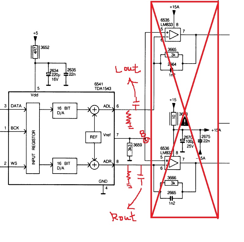
I move away the original opamp I/V converter circuit And use a SHUNT resistor(3.3K) and SERIES CAP(100uF) and then output directly.
But there're some white noise in the background although the music can still be recognized (but noisy!)
Is that because I left the point B(Vref) flatten?
I move away the original opamp I/V converter circuit And use a SHUNT resistor(3.3K) and SERIES CAP(100uF) and then output directly.
But there're some white noise in the background although the music can still be recognized (but noisy!)
Is that because I left the point B(Vref) flatten?
Last edited:
Where are the 2 output resistors (from AOR/AOL to GND) ?
I’ve draw on the pic.
Ah, those red things. OK then, what do you mean 'flatten' ? Everything seems OK provided you got the right values for RVref and RLoad resistors.
I had a number of TDA1543 chips, remember having the same problem from cold joint between RLoad resistors and ground.
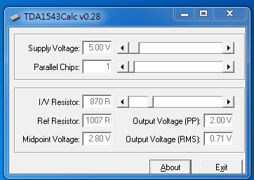
Edit: here the calculator (windows .exe)
https://www.diyaudio.com/forums/digital-line-level/143219-diy-dac-1543-a-7.html#post1831492
I had a number of TDA1543 chips, remember having the same problem from cold joint between RLoad resistors and ground.
Edit: here the calculator (windows .exe)
https://www.diyaudio.com/forums/digital-line-level/143219-diy-dac-1543-a-7.html#post1831492
Last edited:
I tried to modified the schematic and solved the white noise problem
The schematic has been showed below
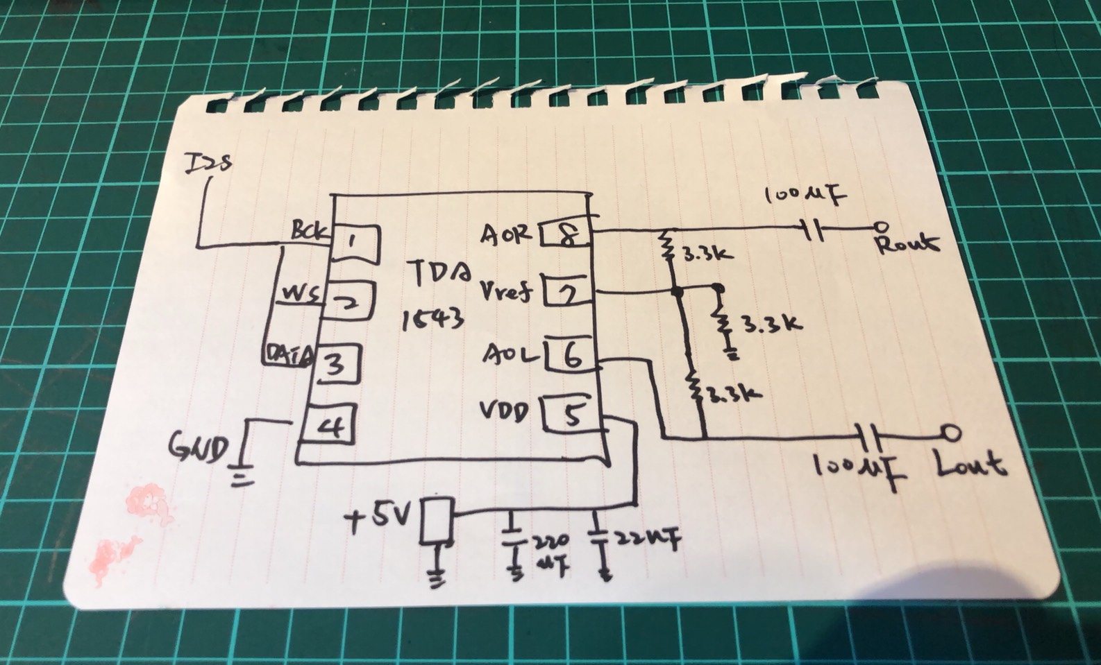
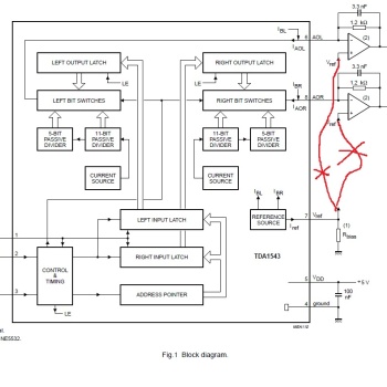
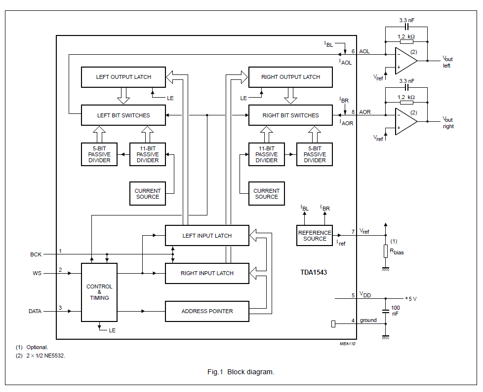
The main concept of this schematic is to use the Vref as a reference "Ground" to the AOL and AOR I/V converter circuit.
Just like the reference block diagram that datasheet suggest(It uses the virtual short of the OPAMP to set a reference ground for AOL and AOR)
But there's also some problem of the sound.
The bass is totally gone.
It's not just a subjective consciousness.
The prove is when I playing a string quartet.
Sound of the Cello part is much weaker comparing to the original OP I/V converter.
The imbalance of the sound can be observed in other music also.
Do anyone knows the reason?
The schematic has been showed below
The main concept of this schematic is to use the Vref as a reference "Ground" to the AOL and AOR I/V converter circuit.
Just like the reference block diagram that datasheet suggest(It uses the virtual short of the OPAMP to set a reference ground for AOL and AOR)
But there's also some problem of the sound.
The bass is totally gone.
It's not just a subjective consciousness.
The prove is when I playing a string quartet.
Sound of the Cello part is much weaker comparing to the original OP I/V converter.
The imbalance of the sound can be observed in other music also.
Do anyone knows the reason?
Last edited:
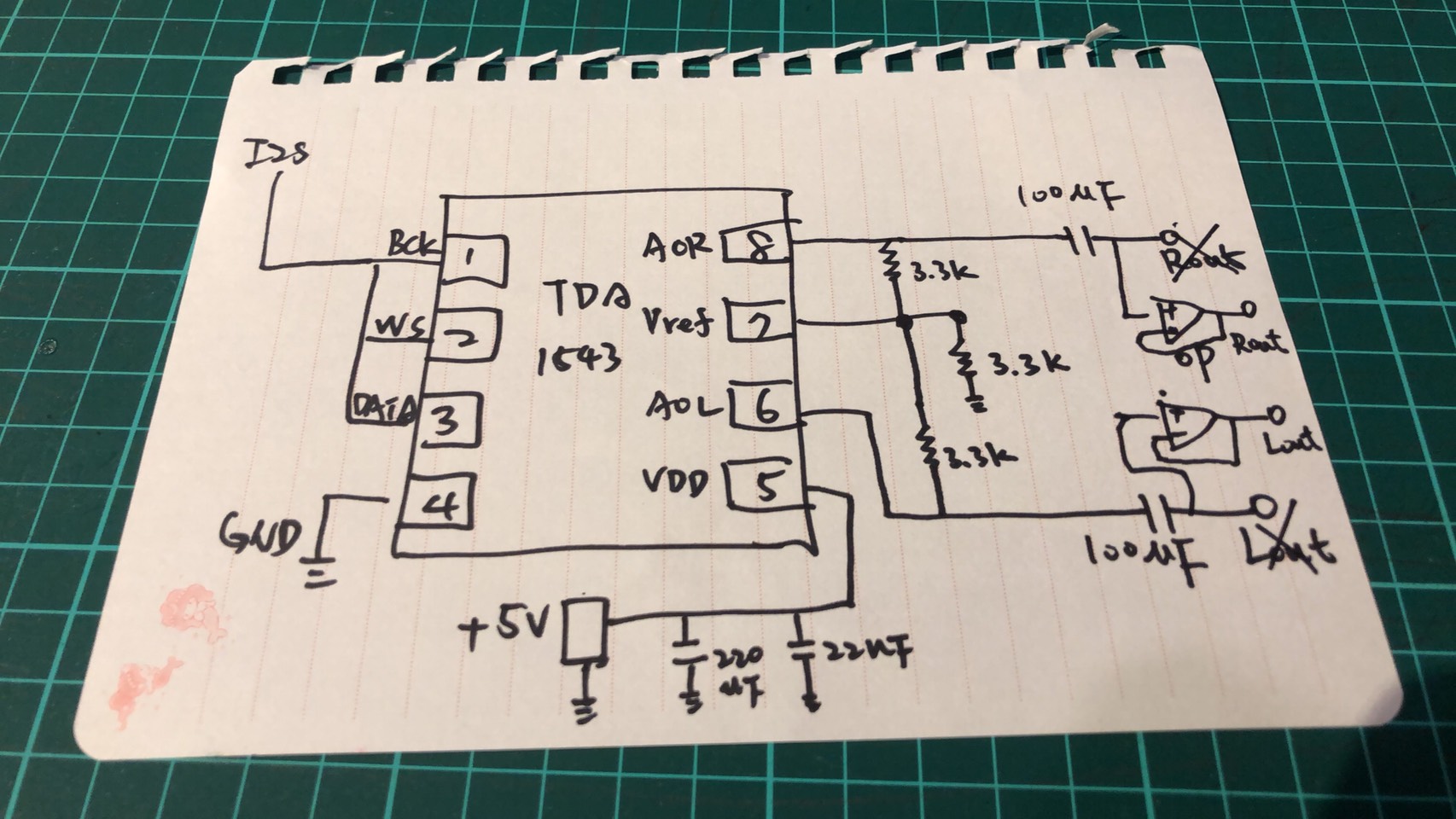
I/U resistors( from Aor and Aol in your schematic ) must be connected to ground not to V ref
It will be some white noise at the background as I mentioned before.
But I don't know why.
Connect to Vref solve this problem.
I added a OP buffer after the passive i/v and the BASS comes back.
But there's still some distortion occurred as the music comes to the largest dynamic.
I guess maybe the value of the resistor still needs to be fine tuned.
Totally agree with your point abraxalito
That explain why is there still distortion now.
I think that’s why the philips guys used the OP amp as a IV converters that can refer to the Vref with it’s virtual ground but isolates the sink current(IBR IBL on the datasheet) simultaneously.
So Maybe that’s also why veterans use the external Voltage supply for the Vref.
But I’m trying to modify the IV converter with the native PCB so there is no external voltage source
Your choice of 3k3 for I/V resistor doesn't work with TDA1543 - its too high a value, bound to result in clipping. For 5V supply you can only get 2V swing at the output hence you need an I/V resistor of 820ohm. Then adjust the output voltage (pins 6 and 8) with a resistor between pin7 and GND to get 2.8V.
Your choice of 3k3 for I/V resistor doesn't work with TDA1543 - its too high a value, bound to result in clipping. For 5V supply you can only get 2V swing at the output hence you need an I/V resistor of 820ohm. Then adjust the output voltage (pins 6 and 8) with a resistor between pin7 and GND to get 2.8V.
Thanks for your suggestion I'LL try the value.
According to the calculator that savvas kindly offered.
The Rref should also change to 1K ohm right?
I believe that 2.8V is so called the midpoint voltage right?
What is that means?
I tried my best to check the Devil you mentioned already
But I do found a strange point.
When I parallel the 3.3K at AOL AOR to ground and measured them
They will down to 2.8K but I can’t explained why.
And sorry for one more question
Do you mean the Vref port just needs to use a shunt Rref to ground without connect to any point?
But I do found a strange point.
When I parallel the 3.3K at AOL AOR to ground and measured them
They will down to 2.8K but I can’t explained why.
And sorry for one more question
Do you mean the Vref port just needs to use a shunt Rref to ground without connect to any point?
Last edited:
Thanks for your suggestion I'LL try the value.
According to the calculator that savvas kindly offered.
The Rref should also change to 1K ohm right?
I believe that 2.8V is so called the midpoint voltage right?
What is that means?
It could be higher, the DDDAC (16x1543) had 3.2-3.4V target voltage. I've read many suggestions for one with regards the supplying voltage e.g.
Pavouk's (5V) is Rref 1k5 and Rload 2k2
I tried my best to check the Devil you mentioned already
But I do found a strange point.
When I parallel the 3.3K at AOL AOR to ground and measured them
They will down to 2.8K but I can’t explained why.
And sorry for one more question
Do you mean the Vref port just needs to use a shunt Rref to ground without connect to any point?
Again, did you really got the OPA circuit (i.e. opa and cap, resistor) out of the signal's way ?
(by cutting trace or removing them all from pcb)
I don't know to whom you are referring but Vref -> Vref Resistor -> GND, nothing else
There are hundreds (if not thousands) TDA1543 circuits in the net, pointing to that
Take your time, sometimes a little solder bit can cause smoke.
Thank for your kindy feedback and warring!
I remove the OPAMP and all the device in the signal path.
I tried not to cut the path if it's not necessarily.
The old philips CD's used two layers PCB so it's not so hard to check the signal path.
And I usually check the schematic from service Manuel also.
But the service manual for my Philips CD480 got only TDA1541 version on website.
That's why I said "tried my best".
I refer to few of the DIYERS like Peter Daniel.
But the idea from the Vref is from the datasheet that 1543 itself.
I know it's a OPAMP I/V converter circuit.
And I might misunderstand what it metioned..
Again, did you really got the OPA circuit (i.e. opa and cap, resistor) out of the signal's way ?
(by cutting trace or removing them all from pcb)
I remove the OPAMP and all the device in the signal path.
I tried not to cut the path if it's not necessarily.
The old philips CD's used two layers PCB so it's not so hard to check the signal path.
And I usually check the schematic from service Manuel also.
But the service manual for my Philips CD480 got only TDA1541 version on website.
That's why I said "tried my best".
I don't know to whom you are referring but Vref -> Vref Resistor -> GND, nothing else
There are hundreds (if not thousands) TDA1543 circuits in the net, pointing to that
I refer to few of the DIYERS like Peter Daniel.
But the idea from the Vref is from the datasheet that 1543 itself.
I know it's a OPAMP I/V converter circuit.
And I might misunderstand what it metioned..
Calculators I think is to give you a general idea. Doede Douma debates the values from the calculator from DiyHifi. He relies more on his experience from listening as you might also read.
- midpoint recommendation
"on 6 Volt the best midpoint is 2,5 Volt
on 8 Volt the best mid point is 3,85 Volt"
- his recommendation for resistor values is the same with Pavouk's per DAC (i.e. 2k2 / number of dacs).
Also it is widely recommended to push voltage above 5VDC up to 8.5VDC (better THD). True, the datasheet has an example with OPAs but since 1543 is capable for 2Vrms Ι find it unnecessary. Tubes are more popular (there is a dedicated thread)
So, try adjusting to the above (even using trimmers if you can) and see what you get.
Don't be afraid if you fried the chip, I have some, stocked somewhere, will give you at no cost.
- Status
- This old topic is closed. If you want to reopen this topic, contact a moderator using the "Report Post" button.
- Home
- Source & Line
- Digital Line Level
- TDA1543 direct I/V out problem