I am not sure how much gain you need for your mics, but That has some very good appnotes available about designing a front end for mic and line level inputs.
I would recommend to attach one of these designs to aurora in case you want to have mic inputs.
@all: A new version of the control app is available. You can get it here:
Release dspControl 0.9.1 * freeDSP/freeDSP-aurora * GitHub
I would recommend to attach one of these designs to aurora in case you want to have mic inputs.
@all: A new version of the control app is available. You can get it here:
Release dspControl 0.9.1 * freeDSP/freeDSP-aurora * GitHub
Well OK, assume I would like to equalize multi-way loudspeaker using it having only mic in possession.
Is is possible to use its mic input for acquiring of impulse response generated by external measurement software via its analog output? Would it be possible to display measurement result as an dynamic overlay in order to see its changes while applying filters?
Is is possible to use its mic input for acquiring of impulse response generated by external measurement software via its analog output? Would it be possible to display measurement result as an dynamic overlay in order to see its changes while applying filters?
I'm very interested in room correction using FIR filters, but my lack of time and knowledge means I'd need something more than a board - I'd need it in a case with inputs and outputs so I could focus on just getting the settings right...
I guess I'll have to wait for the Kickstarter to succeed and the project to progress.
I guess I'll have to wait for the Kickstarter to succeed and the project to progress.
I am not sure how much gain you need for your mics, but That has some very good appnotes available about designing a front end for mic and line level inputs.
Yeah, sorry for posting so much regarding my research on this subject. The short answer is that it's more complicated than it seems. I guess I was hoping for a low-cost high-quality solution that checks all the boxes.
I need between 20-30dB of gain.
The big takaway here is that all digitally controlled mic preamp solutions that I've found use SPI and NOT i2c... The best solution is the THAT 6266, but it is SPI and therefore would require an i2c to SPI bridge because the Aurora doesn't output the SPI required to control it. :-(
For now, I'm going to use a cheap ebay mic preamp that outputs single ended and manually connect it to the Aurora. Then I'll decide whether I want to design a better pre, or redesign the board with the PCM1865. Maybe the Aurora can also introduce an SPI header for control over the gain stages on this type configuration in the future. This would also be a reasonable solution at that point. However, still more expensive than a solution built into the ADC.
The PCM1865 incorporates the Preamp into the ADC and it's only about ~$2.25 per channel. There are no mic preamps on the market that can come that close to that cost per channel with digital control. Even the INA217 implementation (aka $5 mic preamp) doesn't have digital control, and it would be more expensive per channel than the PCM1865! If I were to do this I would probably remove the AK ADC and DAC and build my own onto the Aurora's DSP/MCU design. I suppose this would be fairly easy. I also suppose the aurora could be redesigned without the ADC/DAC altogether and just have FreeDSP Expansion connectors...
The Aurora is perfect for room correction - and really great as a building point for pro audio but not perfect.
I'm very interested in room correction using FIR filters, but my lack of time and knowledge means I'd need something more than a board - I'd need it in a case with inputs and outputs so I could focus on just getting the settings right...
I guess I'll have to wait for the Kickstarter to succeed and the project to progress.
In all honesty the way the Aurora is designed there isn't much you have to do to connect inputs and outputs to it... I've studied the circuits and I'm fairly positive you can connect directly to the I/O of the Aurora with either balanced or single ended inputs and it will sound perfectly fine, in fact, to spec.
There are these documents detailing what I've found in regards to Single Ended>Balanced Converstions.
http://www.tij.co.jp/jp/lit/ug/tidud13/tidud13.pdf
http://www.ti.com/lit/df/tidrww1/tidrww1.pdf
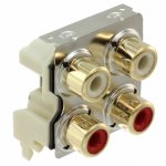
Ultimately, after reviewing these documents I feel like there is no "input stage" required for single ended inputs on the Aurora. So yeah... Just attach the RCA (SE), 1/4 inch (SE/DIFF), or XLR (DIFF) jacks to wire leads, to the Aurora's analog I/O and then mount the jack to your case and you should be OK. Maybe the ESD protection would be nice to have - but still not completely necessary.
Yeah - you'd have to build your own case and solder on the leads to the jacks...
Hello, I have maybe a stupid question. Will this DSP support some kind of mixing matrix with aux sub busses?
E.g. I want to get three aux channels: x * (L+R), R - x * L, L - x * R and then apply a highpass on each of these channels and send to outputs. Then, I would have the L+R signal with lowpass for mono subwoofer. Each of the outputs would also contain some EQ for e.g. compensating CD or dipole response.
E.g. I want to get three aux channels: x * (L+R), R - x * L, L - x * R and then apply a highpass on each of these channels and send to outputs. Then, I would have the L+R signal with lowpass for mono subwoofer. Each of the outputs would also contain some EQ for e.g. compensating CD or dipole response.
Hello, I have maybe a stupid question. Will this DSP support some kind of mixing matrix with aux sub busses?
E.g. I want to get three aux channels: x * (L+R), R - x * L, L - x * R and then apply a highpass on each of these channels and send to outputs. Then, I would have the L+R signal with lowpass for mono subwoofer. Each of the outputs would also contain some EQ for e.g. compensating CD or dipole response.
I don't really understand your three aux channels example. However, I can say that SigmaStudio is a GUI designed to allow you to create audio flows visually. The Aurora has 8 aux inputs which would allow you connect your CD Player to 2 of those 8 channels. You can also stream high quality USB Audio to the device. In the future we'll probably be able to send Bluetooth Audio or Wifi Audio to the DSP as well (software not developed yet for Wifi/Bluetooth Audio). Then inside the software you can route those input channels into whatever flow you want. The DSP will allow you to create a "matrix" that sends, sums, processes, monitors, or splits signals to whatever output you want.
L/R (CD-Player) -> Aurora ADC Inputs -> Sigma Studio
THEN
L + R -> lowpass filter -> Aurora DAC Outputs -> Mono Sub Output
L -> highpass filter ->Aurora's DAC Outputs -> Highpass L out.
R -> highpass filter ->Aurora's DAC Outputs -> Highpass R out.
Plus you'll have 6 inputs and 5 outputs to spare... And yes SigmaStudio with the ADAU1452 has plenty of processing power to handle this and it has highpass and lowpass algorithms setup already.
This is the Free software that the Aurora is designed for:
SigmaStudio | Analog Devices
A Youtube Video describing the software:
YouTube
Last edited:
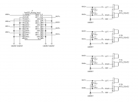
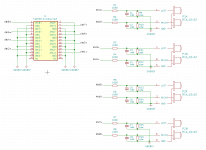
Here is a first take on a schematic for single ended RCA inputs. One board will work for both inputs and outputs, I believe. Please critique. Thank you.

Attachments
Last edited:
I forgot to add a link I wanted to add: http://elias.altervista.org/html/SingleSpeakerStereo.html
I would need to feed some combinations of L+R and L-R into different speakers - at least 3 but maybe more (there is plenty of outputs). As long as I can do this in the Sigma Studio, then I am happy - I will check the documentation. Thanks!
I would need to feed some combinations of L+R and L-R into different speakers - at least 3 but maybe more (there is plenty of outputs). As long as I can do this in the Sigma Studio, then I am happy - I will check the documentation. Thanks!
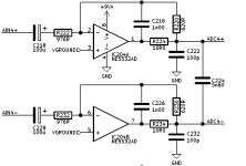
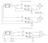
I went into the freeDSPx AnalogIO x8 board and found the "ESD Protection" circuit.
Here is the Aurora:

Here is the AnalogIOx8 (with the extra parts):

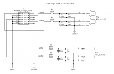
Here is my second take on a schematic for single ended RCA inputs.
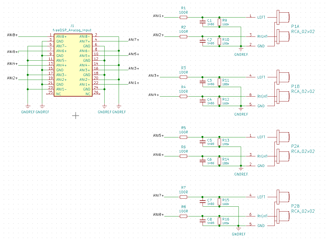
Here is the Aurora:
Here is the AnalogIOx8 (with the extra parts):
Here is my second take on a schematic for single ended RCA inputs.
Attachments
")
JLOP said:- is It possible to daisy chain to have say 10 or 12 outputs (4 ways + several subwoofers)
To add more inputs or outputs you can use the FreeDSP expansion header (1x)(freeDSP Guidelines * freeDSP/WIKI-AND-GENERAL-TOPICS Wiki * GitHub) on the Aurora to connect an additional I/O board. There is a freeDSPx-AnalogIO-x8 (freeDSPx-AnalogIO-x8/GettingStarted.pdf at develop * freeDSP/freeDSPx-AnalogIO-x8 * GitHub) that is pretty much the exact same circuit as the Aurora ADC/DAC. It's the same parts (AK4558 and AK5558) so it would give you another 8in/8out. Or you can use any other freeDSPx add-on board (freeDSP | An Open-Source Low-Budget Audio DSP).
JLOP said:- is it possible to have single ended outputs
Yes, for sure. The Getting Started guide of the freeDSP Aurora (GitHub - freeDSP/freeDSP-aurora: freeDSP ADAU1452 with 8 analog input, 8 analog outputs, S/P-DIF I/O, ADAT I/O, USB Audio Class2, WiFi, Bluetooth) says, "In case of unbalanced sinks leave the negative output unconnected". It also references the inputs by saying, "Unbalanced sources can be connected as well by grounding the negative input".
It's common for balanced inputs and outputs to be "passively" switched to single ended by shorting or ignoring the negative intput/output. Of course the resulting question is whether or not this is the right way to do it. Ultimately it depends on your results. The best way to do it for sure would be to actively convert single ended to balanced in the inputs, and balanced to single ended on the outputs. However, in practice it will still work... And in practice you will get excellent results, as long as the wires are kept short on the single ended signals. They no longer have common mode rejection.
The thing to keep in mind is that balanced signals are usually sent at +4dB and single ended (consumer) signals are usually sent at -10dB. So the getting started guide also suggests that you need to modify the gain settings of the output (in the software) to compensate for the difference.
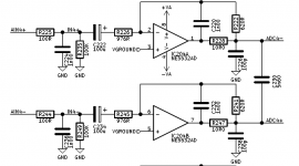
dspverden said:This is not an ESD protection, it is the RFI filter you have added.
Yeah that makes more sense. RFI filter at the inputs, in a metal grounded case would keep the interference to a minimum inside the case. Right!? So putting it close to the inputs will keep the interference out... In theory.
So I have a question... Can that same RFI filter work on the outputs? Also, can the negative pin of the output be grounded? Should it be? I'm trying to determine if we can use the same part for both inputs and outputs (with the RFI and with or without the grounded negative pin).
I'm working on some other schematics to show XLR inputs/outputs, 1/8 inch (3.5mm), and 1/4 inch. I'm also considering drawling up the schematics for an active input/output setup as well. I figured documenting the recommended configuration is the first step.
Last edited:
This is an awesome project! I'm very excited about this. This is almost exactly what I want to do myself, but you guys did it! I would like to help out with the DSP algorithms at some point.
I'm wondering, have you guys ever thought of making a smaller version of this board, but just 4 channels? I would like to put this in a small active speaker.
I'm wondering, have you guys ever thought of making a smaller version of this board, but just 4 channels? I would like to put this in a small active speaker.
I'm wondering, have you guys ever thought of making a smaller version of this board, but just 4 channels? I would like to put this in a small active speaker.
I've been doing some serious thought about creating an "Aurora lite" which would have no ADC or DAC parts - just FreeDSP expansion headers so you can add whatever parts you prefer.
In your case about the small active speaker concept there is a nice amp module on the FreeDSP site. Amp2 (freeDSPx AMP x2 - Google Docs) and Amp4 (freeDSPx AMP x4 - Google Docs).
In your case for the small active speaker I don't know if you need the XMOS chip at all. Unless you want the speaker to have USB audio you wouldn't need to solder on that chip at all. You would want the ESP32->ADAU1452 and then whatever expansion board you want.
By the way - the current Aurora model does in fact have a freeDSP expansion header. So if you want to test out any other freeDSP expansion boards (inputs/outpus/amps/etc) then you can test it with the Aurora and then move onto your own custom PCB when you have it figured out. It's a wonderful prototyping tool because it has a really flexible architecture.
- Home
- Source & Line
- Digital Line Level
- freeDSP-aurora - DSP with 8 I/Os, USB Audio, S/P-DIF, ADAT, Bluetooth and Wifi contro