Sorry if this board was already discussed but I didn't find anything related to it.
I few years ago I paused my diy audio hobby and sold/gifted everything I had built but an year ago I felt the need to start enjoying music once again. In no more than 1 month time I bought the ATC SCM11 curved speakers which I fell in love with at the first note, built a Raspberry Pi 3 + Volumio streamer, built the PeeCeeBee V4H known to most of you and now I was in need of a new DAC which will be used as my main audio source. The requirements were simple:
– Digital input switching. I wanted to use the same DAC whether I am listening from my DIY Volumio streaming device or watching a movie/playing Xbox.
– Good to exceptional sound quality.
After reading an article by a russian author, the PCM1794 datasheet and talking to a friend of mine who works in a professional audio equipment manufacturing company, I decided to try the PCM1794 from Burr Brown for this project. I did a quick search on Aliexpress for readily available PCBs based on PCM1794 and I came across one that looked well made. The PSU part is well separated utilising:
– Four separate transformer windings with 3 bridge rectifiers (MCU+LCD; digital section PSU; analog section PSU)
– Five on board regulators (LM7805 for the uC/LCD, LT1968-3.3V for the AK4118 and PCM1794 digital supply, LM317(5V) for the PCM1794 analog VCC, LM317/337(+-15V) for the opamp supply.
– Utilized ground planes
The board costed only 47$ so I expected cheap capacitors and probably fake AD827 opamps. After 20 days I received the board. I was right, they used cheap caps(except the big filter Nichicons, which seem good) and the opamps are probably fake at this price so I started planning mods to the board.
The first thing I did was to test the board before doing anything so I know if it works as expected. I plugged in all required windings, plugged my set-top box as digital source with an optical cable and flipped the switch…
F**k… The thing is not even working…

Chinese PCM1794 AK4118 board
The first thing I did was to measure all the supplies. I found out that the LT1968-3.3 had 2.0V at its output so the AK4118/PCM1794 didn’t get enough voltage to work. I desoldered the LT1968 and soldered a LD1117V33. It finally worked. Good thing is I don’t have to return it to the seller and I can start with the mods.
After inspecting the board and following some traces I have annotated the photo of the board of all planned mods for convenience.
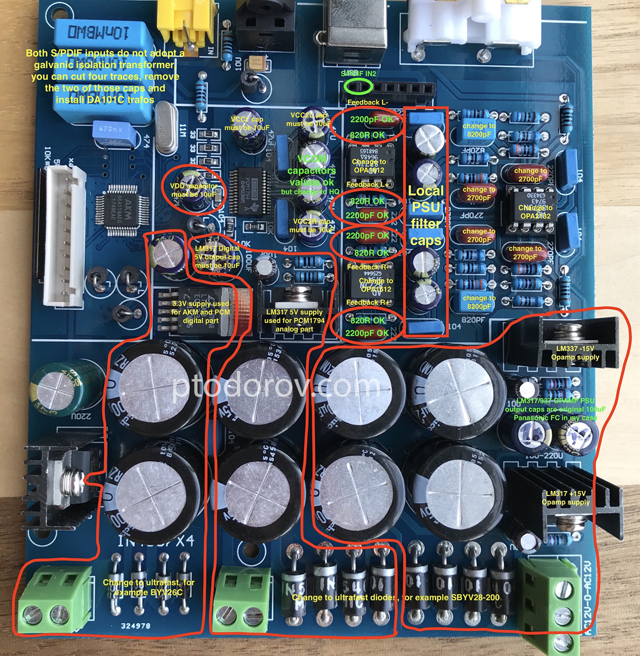
I have done the following modifications:
1. Change all big diodes in the rectifier bridge to SB5A0 fast recovery diodes because the old ones were standard Chinese diodes with shady letters on them.
2. I checked all resistor values according to the following OPA1611(single version of OPA1612) schematic and found out that the 8200pF capacitors were actually 220pF(marked on board as 820pF) and the 2700pF were actually 270pF(marked on board as 270pF). Resistor values were right according to this schematic.
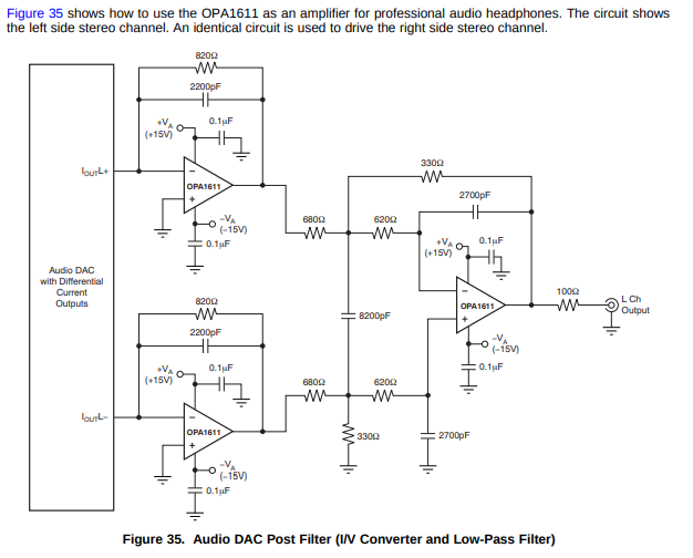
OPA1612 as I/V converter
Changed those to Wima FKS2 capacitors with the right values and also changed the 2200pF metallized film capacitors in the feedback of the I/V stage with same value Wima FKS2.
3. Changed all electrolytic capacitors to Nichicon UPS which are low impedance, high temp range capacitors suitable for PSU usage. Some of the capacitors were 47uF instead of the 10uF according to the PCM1794 datasheet.
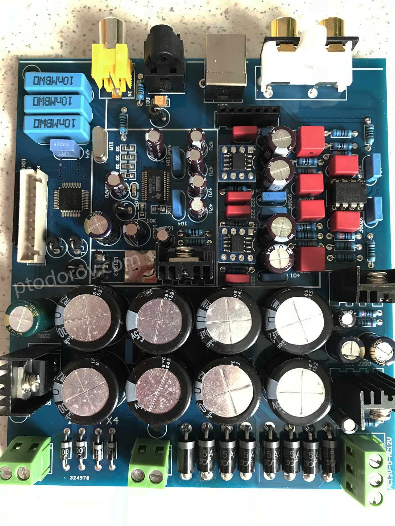
4. The final thing to do was change two of the AD827(probably fake) to two OPA1612 opamps in the I/V stage and change the third AD827 in the differential to single convertor stage to OPA2132.
I will now let the DAC burn in for a couple dozen hours and I will start listening! The next planned mod is to change all regulators to discrete ones based on a new schematic I am now evaluating. I will combine this DAC in one enclosure with my Volumio streamer and the JLSounds XMOS in the next few days. Any other ideas for possible mods/swaps?
I few years ago I paused my diy audio hobby and sold/gifted everything I had built but an year ago I felt the need to start enjoying music once again. In no more than 1 month time I bought the ATC SCM11 curved speakers which I fell in love with at the first note, built a Raspberry Pi 3 + Volumio streamer, built the PeeCeeBee V4H known to most of you and now I was in need of a new DAC which will be used as my main audio source. The requirements were simple:
– Digital input switching. I wanted to use the same DAC whether I am listening from my DIY Volumio streaming device or watching a movie/playing Xbox.
– Good to exceptional sound quality.
After reading an article by a russian author, the PCM1794 datasheet and talking to a friend of mine who works in a professional audio equipment manufacturing company, I decided to try the PCM1794 from Burr Brown for this project. I did a quick search on Aliexpress for readily available PCBs based on PCM1794 and I came across one that looked well made. The PSU part is well separated utilising:
– Four separate transformer windings with 3 bridge rectifiers (MCU+LCD; digital section PSU; analog section PSU)
– Five on board regulators (LM7805 for the uC/LCD, LT1968-3.3V for the AK4118 and PCM1794 digital supply, LM317(5V) for the PCM1794 analog VCC, LM317/337(+-15V) for the opamp supply.
– Utilized ground planes
The board costed only 47$ so I expected cheap capacitors and probably fake AD827 opamps. After 20 days I received the board. I was right, they used cheap caps(except the big filter Nichicons, which seem good) and the opamps are probably fake at this price so I started planning mods to the board.
The first thing I did was to test the board before doing anything so I know if it works as expected. I plugged in all required windings, plugged my set-top box as digital source with an optical cable and flipped the switch…
F**k… The thing is not even working…
Chinese PCM1794 AK4118 board
The first thing I did was to measure all the supplies. I found out that the LT1968-3.3 had 2.0V at its output so the AK4118/PCM1794 didn’t get enough voltage to work. I desoldered the LT1968 and soldered a LD1117V33. It finally worked. Good thing is I don’t have to return it to the seller and I can start with the mods.
After inspecting the board and following some traces I have annotated the photo of the board of all planned mods for convenience.
I have done the following modifications:
1. Change all big diodes in the rectifier bridge to SB5A0 fast recovery diodes because the old ones were standard Chinese diodes with shady letters on them.
2. I checked all resistor values according to the following OPA1611(single version of OPA1612) schematic and found out that the 8200pF capacitors were actually 220pF(marked on board as 820pF) and the 2700pF were actually 270pF(marked on board as 270pF). Resistor values were right according to this schematic.
OPA1612 as I/V converter
Changed those to Wima FKS2 capacitors with the right values and also changed the 2200pF metallized film capacitors in the feedback of the I/V stage with same value Wima FKS2.
3. Changed all electrolytic capacitors to Nichicon UPS which are low impedance, high temp range capacitors suitable for PSU usage. Some of the capacitors were 47uF instead of the 10uF according to the PCM1794 datasheet.
4. The final thing to do was change two of the AD827(probably fake) to two OPA1612 opamps in the I/V stage and change the third AD827 in the differential to single convertor stage to OPA2132.
I will now let the DAC burn in for a couple dozen hours and I will start listening! The next planned mod is to change all regulators to discrete ones based on a new schematic I am now evaluating. I will combine this DAC in one enclosure with my Volumio streamer and the JLSounds XMOS in the next few days. Any other ideas for possible mods/swaps?
Don't connect the I/V opamps direct to the PCM1794, rather insert a passive (CLC) filter between the DAC current out and the -ve input of the I/V opamp. It provides bandlimiting of the fast edges out of the DAC meaning that the opamp has a much easier task. This has been a significant upgrade on my own DACs which use active I/V, making the sound holographic.
While most of the output configurations that I have seen for the pcm1792/4 are fairly simple, I am surprised that there aren’t any resistors at the least before the op amps.
The output on this board looks like the suggested/data sheet implementation, at least after adjustments to it as it had been delivered.
I would try the opa1612 op amps or some of the latest Burson modules if you decide to keep it.
Those filter caps were a great move, and would keep playing with the power supplies after the diodes. Snubber circuits on the diodes would help also, along with an X cap .1uf on the incoming ac power.
I would try just some standard 100 - 220uf after the lm317 regs and see if they work better than the FCs. Have yet to hear an FC that sounded good in whatever position. It appears you’re using some decent, low loss/low noise parts around the chip, that will go a long ways.
I have found that fast recovery diodes may sound different and affect the spectrum that way, but the smoothest are from those that are also soft recovery. For small 3a applications the nte571 works very well, are relabeled Philips parts.
Would you be a bit more specific about that, please?I'd be interested to apply that to a very old unbalanced Iout dac, tda1543 if it makes sense as it's using a lm833 for i/v stage, not a modern fast op-amp.Don't connect the I/V opamps direct to the PCM1794, rather insert a passive (CLC) filter between the DAC current out and the -ve input of the I/V opamp. It provides bandlimiting of the fast edges out of the DAC meaning that the opamp has a much easier task. This has been a significant upgrade on my own DACs which use active I/V, making the sound holographic.
pachy, reading your start thread i do not get the reason for the mods.
You asume that the parts give not the right sound. Why did you not discribed what was wrong with the sound of the origenal parts and make some measurements like ThD, noise harmonics footprint. So that you after the mods can see what made the difference.
You asume that the parts give not the right sound. Why did you not discribed what was wrong with the sound of the origenal parts and make some measurements like ThD, noise harmonics footprint. So that you after the mods can see what made the difference.
Also, if you can use some polystyrene capacitors in the filters, along with the polypropylene that you have, will help the sound. The polystyrene give more crisp treble details, while the polypropylene tend to give more punchy dynamics, bass details.
I’m sure it sounds much better now than when you received it; not working!
I’m sure it sounds much better now than when you received it; not working!
Would you be a bit more specific about that, please?
Here is an example filter I recently posted to another 'Digital Line' thread : IV Opamp converter after DAC: which of the two circuits?
I'd be interested to apply that to a very old unbalanced Iout dac, tda1543 if it makes sense as it's using a lm833 for i/v stage, not a modern fast op-amp.
Certainly looks to make sense to me. Do remove the cap across the feedback resistor when you add in the CLC, as that's no longer needed.
Last edited:
Why don't you try it with and without the filter and see how it sounds? That's the only way find out if its a good idea or not. Some kind of filter between the dac and I/V input can help improve sound quality for many dac chips. It depends how much clock and or other HF noise is coming out of the dac outputs. The HF noise can cause slew-induced distortion in the I/V amp, which if that happens tends to worsen sound quality.
However, clock noise tends to be a bigger problem with older dac chips as compared to at least some of the newer ones. Probably not a good idea to do that with an ESS Sabre dac because HF noise is relatively small and any resistance between the dac outputs and I/V will increase HD. However, a single cap across the outputs may still be an option even for Sabre's.
However, clock noise tends to be a bigger problem with older dac chips as compared to at least some of the newer ones. Probably not a good idea to do that with an ESS Sabre dac because HF noise is relatively small and any resistance between the dac outputs and I/V will increase HD. However, a single cap across the outputs may still be an option even for Sabre's.
Don't connect the I/V opamps direct to the PCM1794, rather insert a passive (CLC) filter between the DAC current out and the -ve input of the I/V opamp. It provides bandlimiting of the fast edges out of the DAC meaning that the opamp has a much easier task. This has been a significant upgrade on my own DACs which use active I/V, making the sound holographic.
Thanks for your suggestion abraxalito. I am not sure that a CLC before the I/V will do more good than harm but I will try and listen how it sounds, as you see in the schematic above, there is a low pass filter in the differential to single converter already. Forgot to mention that I also have galvanic isolation and reclock on the XMOS board that supplies the S/PDIF to the DAC and they are fed with a separate PSU. I will post pictures later.
While most of the output configurations that I have seen for the pcm1792/4 are fairly simple, I am surprised that there aren’t any resistors at the least before the op amps.
The output on this board looks like the suggested/data sheet implementation, at least after adjustments to it as it had been delivered.
I would try the opa1612 op amps or some of the latest Burson modules if you decide to keep it.
Those filter caps were a great move, and would keep playing with the power supplies after the diodes. Snubber circuits on the diodes would help also, along with an X cap .1uf on the incoming ac power.
I would try just some standard 100 - 220uf after the lm317 regs and see if they work better than the FCs. Have yet to hear an FC that sounded good in whatever position. It appears you’re using some decent, low loss/low noise parts around the chip, that will go a long ways.
I have found that fast recovery diodes may sound different and affect the spectrum that way, but the smoothest are from those that are also soft recovery. For small 3a applications the nte571 works very well, are relabeled Philips parts.
Thanks for suggestions, phase! As you can see in the last picture I have installed 2x OPA1612 in the I/V stage already, followed by an OPA2132. I am still letting everything burn in for some hours before listening to the setup.
I usually use snubber capacitors only on generic diodes like the 1Ns, with Schottky they are not mandatory but an RC snubber on the transformer secondary winding is a good idea, I should add one.
I have a DIY AC filter before the R-Core transformer which is not in the pictures, I will post pictures of the full setup later.
After the LM317 I prefer using <47uF as per the datasheet which says any larger value doesn't improve loop stability and output impedance. I will change the FCs to the low impedance PSU's also, thanks for the suggestion.
pachy, reading your start thread i do not get the reason for the mods.
You asume that the parts give not the right sound. Why did you not discribed what was wrong with the sound of the origenal parts and make some measurements like ThD, noise harmonics footprint. So that you after the mods can see what made the difference.
I didn't even bother listening to the original setup, the components were dirty cheap and their values were wrong. I have just listened to it for 1 minute through my TV's analog input with TOSLINK from my set top box to test if it was working after I changed the defective LT1963 and I have also listened it for 1 more minute after the mods so I was sure I didn't break something. Despite listening it through a 0.20$ TV speakers I heard there was an improvement. I guess the AD827 were fake and that made the difference so noticeable.
Its true there's a noise penalty - the noise gain of the I/V stage goes shooting up above the audio band. Can't get around that, its inherent in having a cap to 0V.
@Markw4 - the filter's not suitable for ESS DACs as its designed to be fed by a true current source i.e. a high output impedance. In practice it works fine so long as the output impedance is higher than 100X the load impedance - so here, at least 3k.
@Markw4 - the filter's not suitable for ESS DACs as its designed to be fed by a true current source i.e. a high output impedance. In practice it works fine so long as the output impedance is higher than 100X the load impedance - so here, at least 3k.
I didn’t see the opa1612 noted, just the 2132, sorry I missed that. Great to have the ac line conditioning in place early on, is a great addition that will make it easier to evaluate everything you’re doing.
I always shoot for a target esr of an output capacitor for an lm317 to be .3 ohm, is damped with that.
I always shoot for a target esr of an output capacitor for an lm317 to be .3 ohm, is damped with that.
Thanks for your suggestion abraxalito. I am not sure that a CLC before the I/V will do more good than harm but I will try and listen how it sounds,
I am looking forward to reading your feedback on how it sounds.
... as you see in the schematic above, there is a low pass filter in the differential to single converter already.
Yes I noticed that, its standard practice and I've built and modded several like that myself. However, it seems very important subjectively to prevent the DAC's fast edges from reaching any active circuitry. Doing it after an active stage, the damage (in terms of IMD) is already done.
I read of a very interesting comparison over on PTA a couple of days ago. Let me find the link : Audio Fur and the Border Patrol DAC | Part-Time Audiophile
The key paragraph is this one, written by Herb Reichert :
I use Chesky recording sessions to review headphones because I can compare what I hear live to the sound coming off the so-called “mike feed.” The Border Patrol DAC reproduced the church walls, the reverb, the positions on the floor where the musicians were standing, and all the subtle breathiness of Macy Gray’s voice. With the Benchmark, the majority of that information (which is definitely on the master file and appears via David’s $100K MSB DAC and via my Holo Spring DAC) disappeared !!! Your neutral DAC “stripped” away information that is unquestionably on the master file. Not to mention the BM DAC made it sound hard cold and harmonically threadbare. I call this subtractive distortion.
Would it be possible that the noise generated by this filter to be something similar with the tape on reel to reel or the background noise of the vinyl where you have similar perceptions? You know...there are very interesting studies coming from the neural and cognitive sciences where they treat all sorts of attention problems with White Noise listening.It seems that some noises have the ability to enrich our perception while hiding some other noises.Basically the perception of the distortion is Noise, but our brains are made by nature to hear what noise has a repetitive pattern and skew the attention from irrelevant noise to meaningful noises.White noise is completely random and has the ability to calm us while hiding repetitive or meaningful noises .
- Home
- Source & Line
- Digital Line Level
- Improving a cheap chinese PCM1794 DAC