Hi
First a small intro..
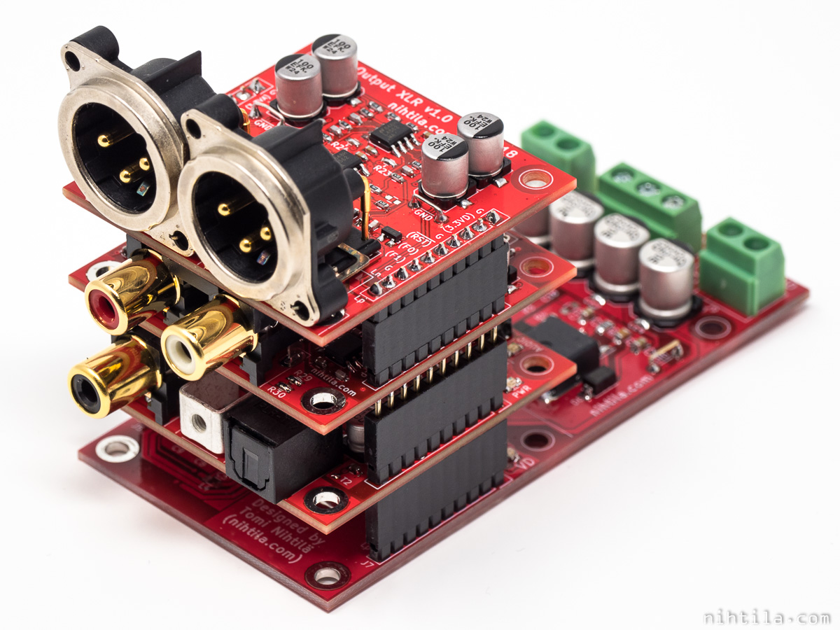
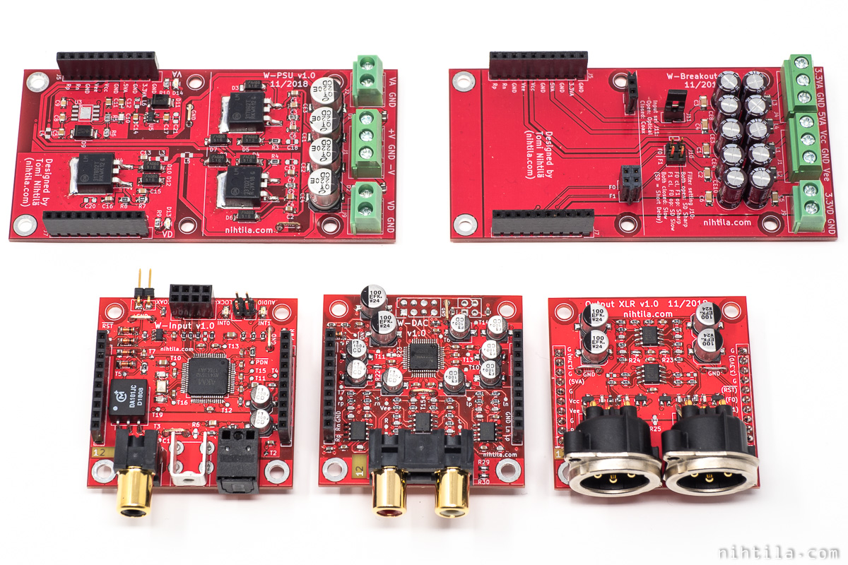
I have designed a tiny DAC based on AK4490 which is part of my small modular DAC design. I can tell (or open another thread) about the project later but here are photos to show what it is about. So the DAC itself is only 50x50mm. The boards are stackable with Input board, DAC, and balanced output board, and breakout and PSU board as base board.
I built the prototypes during holidays and everything is functional. At test bench the first THD figures I got out of it were not impressive so I have been playing with it this week to improve the numbers. However, I am still not close to the best results I have seen so I would be keen to hear experiences on how to improve THD+N. I know many have played with this IC and some have been meausring it as well. I know some designs have ended up in commercial products so I do not expect you to share all secrets but any tips are welcome. Likewise, I will share my experiments. The idea is that this board also ends up for sale; however, I will keep the schematic public and write about the development and results.
I have access to AP at work so I have the big boys' toys to play with.
Something I have found out so far:
So I have got from -93 dB to -108dB (0dBFS), the latter with 2200uF on VREF, voltage kept at 5V. Obviously these have been ugly mods and it can be tricky to fit lots of capacitance on such a tiny board. I also have some layout changes I will do for next revision. I probably will also make a bigger board for experimenting but will see now what I can get out on that form factor.
The caps I have tried so far are basic bulk caps. I have ordered some polymer caps and will try when I get them.
Things I'd been keen on hearing experience on:
I have checked AKM evaluation board (manual) in detail, and it seems a bit off if they have really got the numbers and figures on that.
And while I am open to all feedback, I am really after measured differences here.
----------
And finally some figures where I am now at:
Key figures:
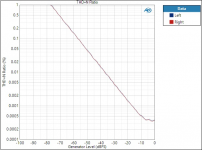
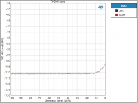
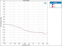
THD+N ratio vs amplitude (I like dBs but forgot this to %), THD+N level vs amplitude, and THD+N vs frequency, and FFT 1k 0dBFS plots below.
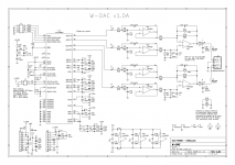
I also put schematic. Basically on board I have 100n+100u on all supplies, except now in these mods I have soldered extra caps. And as a sidenote, output filter is not a limiting factor here, I have also measured directly from DAC output.
Lots of info, but thanks if you read and can help!")
First a small intro..
I have designed a tiny DAC based on AK4490 which is part of my small modular DAC design. I can tell (or open another thread) about the project later but here are photos to show what it is about. So the DAC itself is only 50x50mm. The boards are stackable with Input board, DAC, and balanced output board, and breakout and PSU board as base board.
I built the prototypes during holidays and everything is functional. At test bench the first THD figures I got out of it were not impressive so I have been playing with it this week to improve the numbers. However, I am still not close to the best results I have seen so I would be keen to hear experiences on how to improve THD+N. I know many have played with this IC and some have been meausring it as well. I know some designs have ended up in commercial products so I do not expect you to share all secrets but any tips are welcome. Likewise, I will share my experiments. The idea is that this board also ends up for sale; however, I will keep the schematic public and write about the development and results.
I have access to AP at work so I have the big boys' toys to play with.
Something I have found out so far:
- 5V line (goes to VDDR/L and VREFR/L) is a sensitive one; my initial THD at 0dBFS was -93dB and I saw weird sidelobes on FFT. Apparently the bench PSU providing this was not good enough, after changing to the PSU baseboard I got rid of those. I suspect VREFs are the more sensitive ones. Need to do more tests on this.
- Adding large capacitance on VREF improves THD+N significantly (as is known - although datasheet does not say it anymore!). However, my THD+N vs. frequency still shows elevated distortion at lower frequencies.
- In fact, VREF capacitance seem to matter the most, even removing other caps do not change performance much.
- I see THD+N sweet spot at around -6dBFS.
- Increasing VREF (I've only tried 6.2V as my caps were 6.3V) improves THD+N ratio slightly at lower signal levels, close to full-scale things get worse. THD+N level actually remains constant but ratio improves due to increased signal level. Obviously this improves SNR directly.
- Playing one channel at a time shows an improvement of around 2dB to stereo.
So I have got from -93 dB to -108dB (0dBFS), the latter with 2200uF on VREF, voltage kept at 5V. Obviously these have been ugly mods and it can be tricky to fit lots of capacitance on such a tiny board. I also have some layout changes I will do for next revision. I probably will also make a bigger board for experimenting but will see now what I can get out on that form factor.
The caps I have tried so far are basic bulk caps. I have ordered some polymer caps and will try when I get them.
Things I'd been keen on hearing experience on:
- Capacitor type/quality, capacitance seem to be key factors here but what about the type of cap, its ESR and so on?
- Separating VREFs from VDDs, separating channels?
- Separate regulators for VREFs and VDDs, having them locally close to the IC?
- Any specific layout tips?
I have checked AKM evaluation board (manual) in detail, and it seems a bit off if they have really got the numbers and figures on that.
And while I am open to all feedback, I am really after measured differences here.
----------
And finally some figures where I am now at:
Key figures:
- Full scale output level: 2Vrms
- THD+N at 0dBFS: -108dB
- SNR/DR: 119 dBA
- Crosstalk at 10kHz: around -130dB
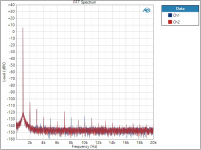
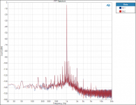
THD+N ratio vs amplitude (I like dBs but forgot this to %), THD+N level vs amplitude, and THD+N vs frequency, and FFT 1k 0dBFS plots below.
I also put schematic. Basically on board I have 100n+100u on all supplies, except now in these mods I have soldered extra caps. And as a sidenote, output filter is not a limiting factor here, I have also measured directly from DAC output.
Lots of info, but thanks if you read and can help!
Attachments
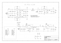
Oh, and here is schematic of the PSU baseboard. So all power lines go through pinheaders which is of course not ideal.
As I mentioned, first round of measurements were done with bench PSUs powering all supplies. See the resulting 1kHz FFT! I haven't seen such FFT before.
As I mentioned, first round of measurements were done with bench PSUs powering all supplies. See the resulting 1kHz FFT! I haven't seen such FFT before.
Attachments
It looks pretty good.
I would use a lower noise regulator and place it adjacent to the DAC on the same PCB.
And as you already tried, add some large capacitors. I used polymer types.
The FFT from the first round of measurements looks familiar! I saw something similar at one point, where the LDO was not set up correctly, so the ripple rejection was bad.
You have some noise at 1 kHz +/- 50 Hz, +/- 150 Hz and +/- 250 Hz. These are "mixer products" that you get from the 1 kHz tone and hum on the VREF supply.
1. R4 to R7 are too high, loads DAC outputs and rise THD. Try to increase them at least to 2k7-3k9. Yours value mean that high-resistance Sennheiser HD800 could be used straightly with DAC outputs while coil inductance would filter out aliases...
2. Try one stage 3-order Bessel envelope filter based on the fully-differential THS4131.
Page22:
http://www.ti.com/lit/an/sloa054e/sloa054e.pdf
3. Series supply-regulators are ugly, go to shunt ones.
2. Try one stage 3-order Bessel envelope filter based on the fully-differential THS4131.
Page22:
http://www.ti.com/lit/an/sloa054e/sloa054e.pdf
3. Series supply-regulators are ugly, go to shunt ones.
1. No. The DAC will not see a load equivalent to the resistor values. It will be much higher. I would rather reduce the values to reduce the noise. I used 220 ohm in the RTX6001.
2. I don't think this will improve the distortion. It will give a higher load on the DAC.
3. As long as the output impedance is low enough and the noise is very low, the regulator type should not matter. Can you measure the difference as nihtila asked for? I used an LT3042 in the RTX6001.
@ nihtila
I also found that increasing the VREF increases the distortion when close to full scale. Below -7dBFS the distortion was actually lower with a 7 V suply compared to a 5 V supply!
Thanks for the comments.
@bnae38
Have you had the cap after the R, to make RC filter? Or probably cap on both sides.
@BesPav
1. The impedance of the filter caps are quite high at lower (=audio) frequencies so the loading of the DAC should be within specs; and at DC there is basically no loading at all. As Jens said, going higher resistances will introduce extra noise. Even if this is nothing extremely quiet, -112 dBV or so noise at audio band is quite low and easily increases when resistors go to k-range.
2. Fully differential circuits load even more as you need to have low resistances to get noise low. Unless you buffer the outputs, and then you don't win anything anymore. Fully differential opamps seem to be more expensive as well.
@JensH
How was your THD+N vs frequency? Did you get it nearly flat? If I would get it nearly flat with similar level to around 5kHz, that would be excellent. In various AKM datasheets they have this shape of graph for small VREF cap values. Mine was not small but it was a massive 2200u cheap bulk with ugly mod. I hope better quality caps in smaller form factor would improve this.
Local regulators are something I do want to try, but probably not possibly on this board.
Last edited:
Sallen-key type (VCVS) filter circuit have unequal impedance, seen from opamp's +input and -input and it may introduce distortion at opamp's input which is not cured by NFB.
Solutions are choose appropriate opamps or insert same impedance to the +input side , or bootstrap whole opamp i.e. bootstrap their rails.
Solutions are choose appropriate opamps or insert same impedance to the +input side , or bootstrap whole opamp i.e. bootstrap their rails.
I agree with Jens suggestion to use a better regulator and place it adjacent to the DAC on the same PCB using +15V as the source. I think LP3878 probably has noise levels low enough, but the ripple rejection >1kHz is nothing to write home about.
In the meantime you could try out remote sensing for the regulator you have. Connect R5 and C10 on the regulator board with a (short) wire to +5VA on the DAC board.
Also, in general, MFB type filters have lower distortion than Sallen-Key types, due to avoidance of common-mode distortion in the opamp. However with LM4562 this should not be a major issue.
And having the "sweet-spot" for THD at -10 to -6dBFS in very normal for delta-sigma converters.
You have reached -110dB at -10dBFS, I think that is quite respectable compared with the datasheet, how low distortion do you aim to get out of this chip? Which AP analyzer are you using? You may be getting close to its limits as well.
I know my regulators and powering scheme is not the best but it's also difficult to guess what makes a difference. I looked at some other regulators, like LT3042 Jens mentioned, and the figures are from a different planet indeed. Especially noise and PSRR. Noise may not be an issue as ojg said, but there's massive difference in PSRR between those regs. I need to study this a bit more, I didn't even know there are such low figures available.
I'm not a filter expert, Shinja's point is noted and something I have not been considering. However, I still think it's not an issue here. CM distortion in SK filters is something I am aware of but it should not be an issue with LM4562 which handles CM very well (according to Douglas Self's measurements). I have characterised the filter part with AC signal, I still need to do that with the DC level as well.
The last measurements I did I think was with massive bulk caps at VREF and there I didn't really see THD+N deteriorating close to maximum level anymore. That is the graph I have attached in the first post. So minimum is around -108dB.
I am very happy with these results and if I can implement mods on the PCB that get me these figures, it is excellent for this project. But there is of course some academic interest in what can I do to push the performance even further. And then possibly use that knowledge on another board.
I should get polymer caps today or on Monday, then do some cap experiments. I will do a bit of research on regulators during the weekend and order in some and experiment with those later next week. Then see what I can implement on this board.
I am using APx555 so there is still some headroom left.
I am using APx555 so there is still some headroom left.
Lucky you! Then please soldier on to find out where the last bits of performance are.
Lucky you! Then please soldier on to find out where the last bits of performance are.
I know. I don't think anyone else in the office considers that as a benefit
Your values for R4,R5; R8,R9 - seem to be low. (560)
The AK4490's recommended load is about 2kohm.
Did You try to raise these values?
Sure that needs a re-calculation.
Ciao, George
See the whole circuit and not just resistor values. Resistors connect the output to the opamp input = extremely high impedance. It is the capacitors that matter, and their value is tens of kohm at 1 kHz, for example, when doing basic THD measurement.
Try capacitance multiplier on PSU:
Capacitance Multiplier Power Supply Filter
Capacitance Multiplier Power Supply Filter
I got some polymer caps yesterday and did a quick measurement after work. No improvement, in this case it seems to be just about the capacitance and not really how good the cap is. This was quick and ugly test though, it's a bit tricky to put caps on my tiny PCB.
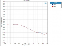
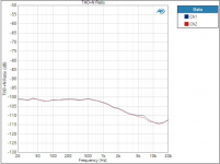
I also tried a quick mod by wiring the 5VA reg voltage sensing point from the DAC board, as suggested by ojg. This is quite ugly mod also as the wire is not that short. THD+N at 1kHz remained the same BUT lower frequency distortion got better, see graphs (this is with 680u tantalum polymer I was able to fit on the board, first normally and second with the sense wire mod). This gives some confidence that on-board regulation would improve the lower frequency distortion, and hopefully will push the 1kHz range down as well when all are on solid copper instead of flying wire.
I have decided to make a test board for the AK4490 before re-spinning the W-DAC board. I will try to make and order it during the weekend. I want to try better regulators on that board, along with different cap configurations. This gives better insights on how to modify the W-DAC board. This is something I should have done first, but...
So it will probably take 2-3 weeks before there will be significant updates on this.
Attachments
Last edited:
Your issues would seem to reflect LP3878 noise levels, which are quite high below 1-2 kHz in particular according to the datasheet. In hindsight (which proverbially is 20/20, I know), maybe not the best candidate for +5VA. I'd suggest trying a larger capacitor on the BYPASS pin, which would seem to be filtering the voltage reference. The datasheet insists on something low leakage - if you have some 220-470 nF films around, try one of those.
It is unfortunate that the capacitor in parallel to R1 is already used for some pole/zero trickery, but what you could try is another RC combo in parallel to both - an electrolytic in series with maybe the same value as R2 (or half that). This would make the regulator act like a 2 V (or 1.5 V) one for AC, with correspondingly reduced noise gain. I'd try 1 kOhm + 10-22 µF (low ESR not needed for obvious reasons... quite the contrary, you want lowish leakage).
With as much capacitance as you have on the VREF pins now, a bit of series R (as mentioned before) is in fact also worth a shot. RC filtering always works much better if R isn't just regulator output impedance, for obvious reasons.
Using two mono DACs in differential output mode avoids a lot of these problems, as the Vref noise subtracts (so it's got inherent PSRR).
Last edited:
Some more armchair-engineering: As much as I like small cute PCBs, it seems in this case it might be limiting the performance you can get. With a larger PCB, perhaps the same size as your PSU board, you would have room for more VREF capacitance and a +5VA regulator.
Why not try a Jung/Didden regulator for +5VA?
It is interesting that the AKM DACS all seem to require lots of VREF capacitance, 1000uF or more, while the similar spec'ed DACS from TI or AD do not have these requirements. What is the inherent difference in DAC design that causes this?
Why not try a Jung/Didden regulator for +5VA?
It is interesting that the AKM DACS all seem to require lots of VREF capacitance, 1000uF or more, while the similar spec'ed DACS from TI or AD do not have these requirements. What is the inherent difference in DAC design that causes this?
Some more armchair-engineering: As much as I like small cute PCBs, it seems in this case it might be limiting the performance you can get. With a larger PCB, perhaps the same size as your PSU board, you would have room for more VREF capacitance and a +5VA regulator.
Why not try a Jung/Didden regulator for +5VA?
It is interesting that the AKM DACS all seem to require lots of VREF capacitance, 1000uF or more, while the similar spec'ed DACS from TI or AD do not have these requirements. What is the inherent difference in DAC design that causes this?
Capacitance requirement can be quite crazy. In my ugly mods there was a significant change still going from 2200u to 2x2200u. But I hope when I get a good regulator on-board it would not require that much anymore. Odd thing in this is also that why AKM removed the graph from AK4490 datasheet (or EVB manual) showing the impact of VREF cap on low frequency THD? And they don't even use large capacitors on their EVB, nor are the regulators on the same board as the DAC. I really doubt they measure the claimed performance on that board.
I will need changes on all boards but the XLR one so I will re-consider the form factor and interface. At least the interface will change, I will likely have 5VD, 5VA, +15VA, and -15VA, and then use on-board regulators for 3.3V voltages and also for 5-7V for VREFs and such. Also remove two pins from one side for simple keying. Therefore, I can think of making the boards larger but will need to check cost impact as well.
It would be nice to have a bit more information on all the supplies other than VREF, such as AVDD or VDDL/R; how sensitive are those to noise and interference. Will try to do some simple tests on the test board when I have it.
- Status
- This old topic is closed. If you want to reopen this topic, contact a moderator using the "Report Post" button.
- Home
- Source & Line
- Digital Line Level
- Improving AK4490 THD(+N) figures