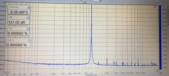
yes, a notch filter would boost the sensitivity indeed. regarding Olivine2, the stated noise floor is below -140db, what actually I get. as for the harmonics, so far I know they were measured with Victors oscillator, powered from an adapter, which may add some. the DAC measured above was powered using Imed power supply + Isobar 60dB filter. got them from a scrapyard when the local hospital was upgrading equipment
anyway, Olivine was the second best investment for this audio madness, next to Siglent SDS1202X-E
WRT Olivine-2, AFAIK it uses PCM1804 which has a (20k BW RMS) noise floor (= dynamic range) of 112dB.
That 'grass' you see at -140dB is not the actual RMS noise floor, this is a narrow band sweep to uncover very low level harmonics. The narrower the sweep bandwidth, the lower the 'grass' will be on FFT. In fact no audio ADC chip exists with a (20kHz BW) -140dB noise floor.
As stated, unless you use a notch filter with this arrangement, most of these super low distortion measurements don't really mean much as there can be harmonic cancellation between DAC and ADC.
Sorry to rain on the party but it's important to understand the results.
T
you are right regarding the above, so do not take these distortion numbers too seriously ")
the major purpose for Olivine I see in the revealing the real consequences from mods done. because I believe in psychoacoustics.
concerning the question can it be used for benchmarking, I can only speak about PreBox S2 Digital, Topping DX3pro and Khadas toneboard, which I own and they have been reviewed by ASR as well. I think an AP analyzer was used there. measuring these DACs with Olivine gave almost perfect match with numbers published.
I can see you are back to EL caps for the I/V stage?
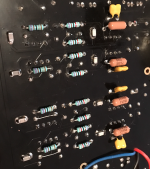
thanks, I removed those elcaps and soldered 0.1uF np0 instead. not really very next to the power pins but it measures even better now. and I would say sounds better as well, kind of "faster" and more "spacious" in headphones, but please this is just what I hear, not necessarily the truth
Attachments
Last edited:
t...soldered 0.1uF np0 instead...
Although we are cautioned to be careful with NP0 ceramics for bypassing due to possible self-resonance issues, as a practical matter some judicious use of NPO and or film bypass caps, or power filter caps, often seems helpful for audio. Perhaps a little distance from the power pins could be a good thing if it adds a little bit of ESR.

thanks, I removed those elcaps and soldered 0.1uF np0 instead. not really very next to the power pins but it measures even better now. and I would say sounds better as well, kind of "faster" and more "spacious" in headphones, but please this is just what I hear, not necessarily the truth
Do you think it might improve or degrade the measured performance if you replace those NP0 caps with X7R caps? I have a bunch of 0.1uF X7R caps but not so many NP0 caps of that value.
Also, do you still have on the board those 0.1uF polyester bypass caps that are at the ends of the power rails for the opamps? If so, perhaps you should also replace them with NP0 caps to see if further improvement can be gained.
Although we are cautioned to be careful with NP0 ceramics for bypassing due to possible self-resonance issues, as a practical matter some judicious use of NPO and or film bypass caps, or power filter caps, often seems helpful for audio. Perhaps a little distance from the power pins could be a good thing if it adds a little bit of ESR.
Very careful worded. I have found that one must experiment and ignore others narrow views!
Sure it will fail often, however when it works out you then have another trick to either share, or keep to yourself.
Your description of the effect of adding the relatively large (in terms of capacitance) film caps to bypass the power rails fits what I experienced very well. In the last few months, I have tried adding various combinations of large PP film caps to the power rails of my 9038Pro board. "Lush" and "smooth" were two adjectives that came to mind when I listened to the DAC board with the added film capacitors.
Ultimately, however, I have decided to remove all the film caps, and even the 0.1uF X7R bypassing caps I also added, from the board. The reason is that I am not convinced that "lushness" or "smoothness" corresponds to better sound quality. For instance, I don't think I've ever heard a female or male voice in real life that is "lush," "smooth," "warm," or "rounded"in the way presented by the DAC with large bypass film caps.
At the end of the day, it's a guess anyway as to what the recorded voice was supposed to sound like. Voices in recordings are almost always 'tweaked' to suite the material, mix or purely just to make, for example a lean sounding voice a bit warmer.
A good example of this is Bradley Cooper's voice in 'A Star is Born' compared to his actual voice in, say an interview. They sound very different.
T
At the end of the day, it's a guess anyway as to what the recorded voice was supposed to sound like.
Hi Terry,
Thanks for the comments. The "guessing" part is what makes this audio hobby so frustrating. No knowing exactly how the original events sound like and what happened in the recording processes makes all the efforts and attempts to tweak a system to make it sound "real" or "good" a wild goose chase.
Not knowing exactly how the original events sound like and what happened in the recording processes makes all the efforts and attempts to tweak a system to make it sound "real" or "good" a wild goose chase.
That may be an overstatement of the issue. What original events sounded like may not matter as far as digital reproduction goes. If digital playback sounds very close to what original master tapes sound like when played back on the original machines used to do the mastering, that should be enough to evaluate A/D and D/A overall accuracy.
If one went further by mixing and matching A/Ds and D/As perhaps we could do some statistical analysis to tease out effects of A/Ds vs D/As.
Obviously, it would be expensive and complicated, but at least one audiophile has done the first part of it already, along with some of the second part. Mostly likely some mastering engineers have done their own comparisons too.
Doing all that at very low cost would probably not be possible. We can at least take home some lessons for what usually seems to get closest to the source in terms of accuracy of reproduction. For dacs, it typically means some combination a very good measured performance, and very detailed yet musical sound quality.
The way to approach that particular combination of things that tend to be associated with accurate reproduction in a diy setting is probably to mostly stick with tried and true basics. Clean design with careful attention to things like power supplies and regulators (perhaps a several regulators dedicated to different loads), low jitter clocking, RF, grounding, low distortion output stages with proper filtering and possibly balanced interconnects, etc.
In particular, starting with a cheap dac and swapping in some easy to change parts is not likely to get one very far in most cases, whether or not particular changes hurt or help accuracy of reproduction (perhaps some of both is common). One big problem with trying to do it is because many low cost dacs are not mod-able enough so as to make it possible to fix all the things that are wrong, which is usually almost everything. Why everything? Because low cost dacs or other audio components are built to a price point and if well designed they should be pretty well optimized for their market sector by the designer(s) to be close to equally compromised everywhere, in a balanced and carefully considered way. Chances of a really good designer making stupid mistakes and building a great dac, but with only a few easily changed bad parts should be very low. Wouldn't be a very good designer in that case.
Last edited:
.... many low cost dacs are not mod-able enough so as to make it possible to fix all the things that are wrong, which is usually almost everything.....
thanks for pointing out this. now it is pretty much clear.
is
transformer connection
Am I doing the right connections from transformer to ES9028PRO board? The board itself don't have input voltages tags. There is not docs about this board, I could not locate one. I bought this transformer in ebay and it is the right one for this board.


My top doubt is about the 15v wires (2 blue and 2 yellow). There are 3 bolts connections (I suppose they are for the 15v)
Am I doing the right connections from transformer to ES9028PRO board? The board itself don't have input voltages tags. There is not docs about this board, I could not locate one. I bought this transformer in ebay and it is the right one for this board.
My top doubt is about the 15v wires (2 blue and 2 yellow). There are 3 bolts connections (I suppose they are for the 15v)
Last edited:
It “looks” correct, however, you will need to verify with an ohm meter which two of the yellow and blue leads are indeed the center or 0V.
The ohms reading should of course be similar between the two yellow/yellow, and the blue/blue. The ohms reading between the two center leads will of course be a lower reading than the other remaining pair.
I hope I explained that so that it makes sense anyways.
The ohms reading should of course be similar between the two yellow/yellow, and the blue/blue. The ohms reading between the two center leads will of course be a lower reading than the other remaining pair.
I hope I explained that so that it makes sense anyways.
It “looks” correct, however, you will need to verify with an ohm meter which two of the yellow and blue leads are indeed the center or 0V.
The ohms reading should of course be similar between the two yellow/yellow, and the blue/blue. The ohms reading between the two center leads will of course be a lower reading than the other remaining pair.
I hope I explained that so that it makes sense anyways.
Thank you so much. I understood and I will do it
Am I doing the right connections from transformer to ES9028PRO board? The board itself don't have input voltages tags. There is not docs about this board, I could not locate one. I bought this transformer in ebay and it is the right one for this board.
...
My top doubt is about the 15v wires (2 blue and 2 yellow). There are 3 bolts connections (I suppose they are for the 15v)
I have exactly the same transformer from China, also ordered off eBay. The two 15Vac secondaries are wound separately, and if you measure the resistance between the a blue wire and a yellow wire, it should be very high -- > tens of mega-ohms (out of range on my Fluke multimeter). The resistance between the blue wires or between the yellow wires should be around several ohms.
To figure out how to connect the transformer 15Vac secondaries to the board, first you arbitrarily combine (simple twisting is fine for this test) the end of a yellow wire with the end of a blue wire to form the "central" or ground connection. This is done with the transformer not connected to the board and before the primary is connected to the AC outlet. The remaining blue and yellow wires and the "central" have to be kept apart securely to prevent shorting. I taped the wires on my workbench so that they could not move. Then you apply AC to the primary and measure the voltage across the remaining yellow and blue "non-central" wires. If the voltage is around 30Vac or higher (mine measured ~37Vac), this "central" configuration is fine, and you can connect the wires to the board accordingly. If the voltage across the remaining yellow and blue wires is close to 0, however, just switch out one yellow wire (or blue wire) with the other yellow wire (or blue wire) for the central, then the two secondaries will be connected properly.
Since you have already connected the 15Vac secondaries to the board, you can just measure the voltage between the screws of the two non-central terminals on the connector. If the voltage is 30Vac or more, then your connection is fine.
Hope this helps.
Last edited:
I have exactly the same transformer from China, also ordered off eBay. The two 15Vac secondaries are wound separately, and if you measure the resistance between the a blue wire and a yellow wire, it should be very high -- > tens of mega-ohms (out of range on my Fluke multimeter). The resistance between the blue wires or between the yellow wires should be around several ohms.
To figure out how to connect the transformer 15Vac secondaries to the board, first you arbitrarily combine (simple twisting is fine for this test) the end of a yellow wire with the end of a blue wire to form the "central" or ground connection. This is done with the transformer not connected to the board and before the primary is connected to the AC outlet. The remaining blue and yellow wires and the "central" have to be kept apart securely to prevent shorting. I taped the wires on my workbench so that they could not move. Then you apply AC to the primary and measure the voltage across the remaining yellow and blue "non-central" wires. If the voltage is around 30Vac or higher (mine measured ~37Vac), this "central" configuration is fine, and you can connect the wires to the board accordingly. If the voltage across the remaining yellow and blue wires is close to 0, however, just switch out one yellow wire (or blue wire) with the other yellow wire (or blue wire) for the central, then the two secondaries will be connected properly.
Since you have already connected the 15Vac secondaries to the board, you can just measure the voltage between the screws of the two non-central terminals on the connector. If the voltage is 30Vac or more, then your connection is fine.
Hope this helps.
I had already used the technic pointed by @phase. I will use your tip next time. Thanks you anyway!
- Status
- This old topic is closed. If you want to reopen this topic, contact a moderator using the "Report Post" button.
- Home
- Source & Line
- Digital Line Level
- China ES9018PRO ES9028PRO 9038PRO mods&upgrades