Once you start paralleling, especially with hi Q MLCC's, tank circuits form and it can affect the sound.
It would depend on the particulars of the implementation. Nobody is suggesting doing what you are warning against with respect to forming high Q tank circuits. Only a very particular solution using film caps (not high Q MLCC's) that is known to work well has been specifically recommended for audio opamp circuit use.
To be clear so that people understand what is being discussed, sometimes people try to use things like C0G or NPO ceramics that work up to very high frequencies as bypass or decoupling caps. Even with X7R material that has lower Q, engineers used to sometimes suggest paralleling them to decade values, such as .1uf, .01uf, and .001uf all in parallel. Later analysis showed it did not work as intended across a wide frequency range because of parasitic inductance associated with the caps. There ended up being multiple high Q resonant tuned circuits that made supply impedance higher rather than lower at many frequencies. Those things are now much better understood and described in some engineering texts.
The situation with the film caps we use in one block is very different. There are none that are less than 10uf and they appear to become ineffective as capacitors up somewhere up in the neighborhood of 100kHz or so, maybe a bit higher. There is no reason to be concerned at this point that high Q resonant circuits are becoming problematic with their use. Also, it is well understood that even smaller value film caps do make good bypass caps at high frequencies, rather X7R should be used for local bypassing. Tantalums are often used in parallel so long as they don't look like good capacitors at very high frequencies and become increasingly lossy instead, which is the the appropriate behavior we would want from them.
Last edited:
slamming the design and summarily condemning it to the dustbin sounds harsh. I bet the manufacturer simply followed whats listed for the demo board for these Sabre DACs hence the 680R values. http://www.esstech.com/files/5114/4095/4310/Sabre_8_2Channel_64PIN_V3_SCH.pdf
I dont see Sabre publishing another paper for 9038Q2M or Pro.
How confident are we about lowering the I/R resistor for the Pro? ANyone tried it with 240R?
I dont see Sabre publishing another paper for 9038Q2M or Pro.
How confident are we about lowering the I/R resistor for the Pro? ANyone tried it with 240R?
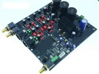
NEW ES9038 ES9038PRO DAC decoder assembled board upgrade to Crystek CCHD-575 | eBay
Same board as the photos the OP posted but
Not the schematics that the OP posted (which seems to be a 9018 board schematic not a 9038)
Same board as the photos the OP posted but
Not the schematics that the OP posted (which seems to be a 9018 board schematic not a 9038)
Pretty sure those 120R resistors are R2 and R11 from the schema you posted, which are controlling the rolloff. The 'Designer' used 120 instead of 100R.
You are correct in pointing out that 680R is a value recommended by ESS. However that was for the 9008/9018, which put out about 4.2mA P-P which results in 3Vrms at the output for 4||DAC.
The 9038 does not have the same level of Iout, and neither does the 9028. Which is exactly what I meant.
Edit: See - DIY ES9038pro Board
Last edited:
Pretty sure those 120R resistors are R2 and R11 from the schema you posted, which are controlling the rolloff. [/URL]
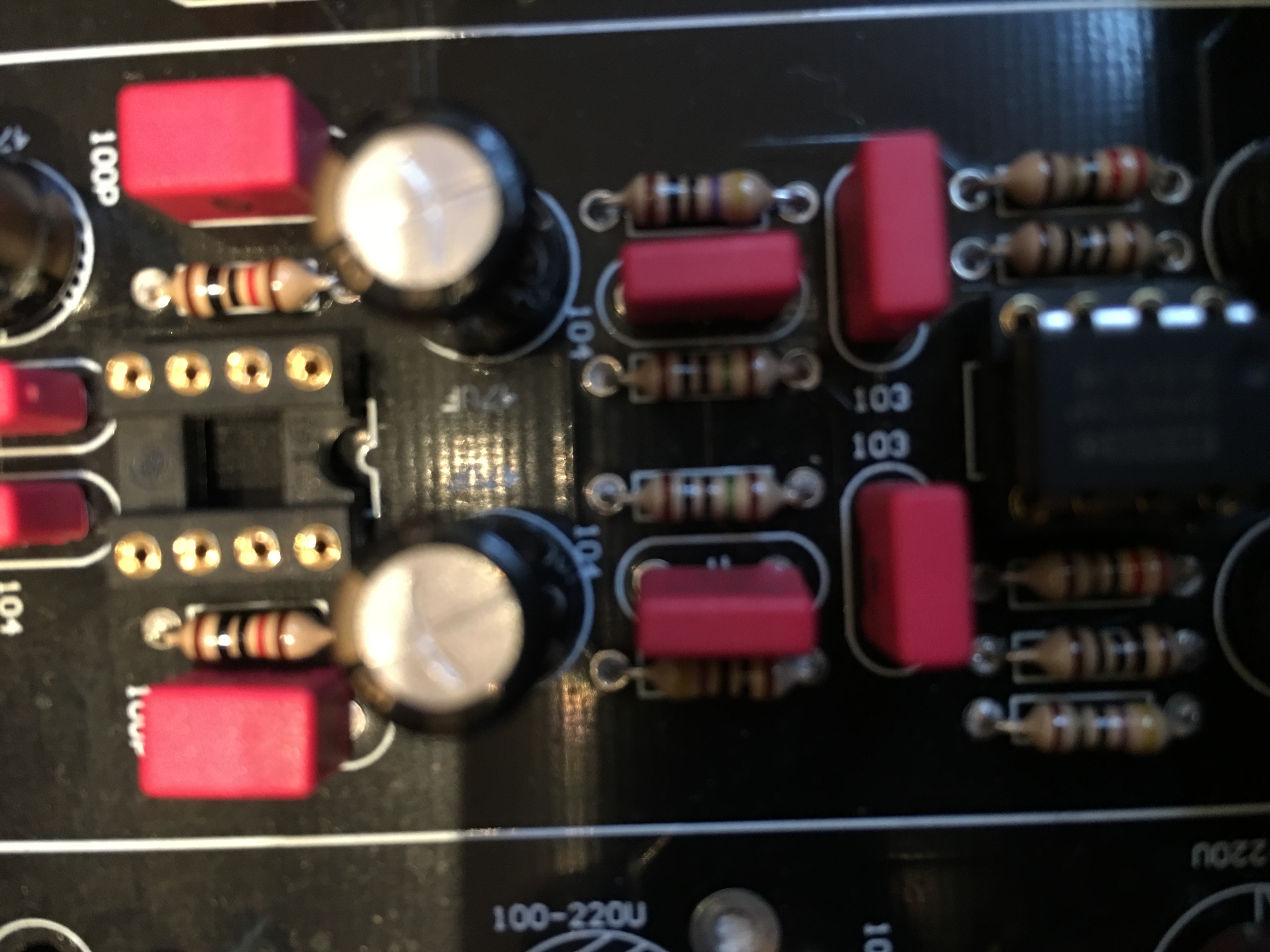
Easy enough to check. Looks like a socket for a dual opamp, right? The I/V resistors would be connected from the outputs back to the inverting inputs. Output pins on dual opamps are 1 and 7, and the inverting inputs are the pins adjacent to the outputs at 2 and 6. What does an ohm meter show between those sets of pins? (with the power turned off, of course
") )
)Are the green Nichicon Bipolar 25V 10uF fakes also?
You mentioned "counterfeit mika CDE capacitors" I dont see any CDEs there seems like the 100pFs are all WIMA. Thanks.
The BP electrolitics seems genuine. CDE 1% Mika 100 pF are the yellow caps in my board.
NEW ES9038 ES9038PRO DAC decoder assembled board upgrade to Crystek CCHD-575 | eBay
Same board as the photos the OP posted but
Not the schematics that the OP posted (which seems to be a 9018 board schematic not a 9038)
The schematics i have are the one the seller provided, as i remember he said the board is the same for 18, 28 and 38 there is a diffent MCU for 18.
Could you please post the schematic you have, just to compare?
@Markw4 Pins 1-2 and 6-7 measure 120 ohms.
@sangram There are lots of 100 ohm resistors there. I would not summarily bad-mouth the implementor of this circuit and say he/she used a 120 instead of a 100 out of convenience. Some DACs are absolute garbage. This one ***might*** just be an odd diamond in the rough.
@idir I will keep you posted of how my replacement caps from Mouser compare with the suspect Silmics. I think the Nichicon FW's on the board are real. The Nover 6800uFs pre-regulation are cheap enough. My board doesnt have silver mica, only WIMA so I can speak for the fake micas.
@idir I dont have the schematics. I am just trying to trace this board myself (of particular interest is the SE output side of things) I will get a better trace once I flip it next time after the caps arrive and I can trace and change at the same time. This board is nothing like the schematic you posted. And I am pretty sure your board and mine are the same. Wait...... it does look like your board has 680 ohm resistors as per your schematics! Blue-Gray-Black-Black-Brown?
Last edited:
@jlw I think we do have the same boards. I believe they use exactly the same boards sice the ES9018PRO through ES9028PRO and ES9038 PRO
Pins 1-2 and 6-7 measure 118 ohms. (- 3 Ohm of my multimeter wires thatwould give 115 Ohm). In my board
Here is the picture of genuine vs whatever is there Elna Silmic II. I did not have 25V so the size is not the same but the colors seem weird. I have check Elna specs and did't find that color pattern therefore assumed they are fake.

When it comes to 680 Ohm Resistor i do not see it here

Pins 1-2 and 6-7 measure 118 ohms. (- 3 Ohm of my multimeter wires thatwould give 115 Ohm). In my board
Here is the picture of genuine vs whatever is there Elna Silmic II. I did not have 25V so the size is not the same but the colors seem weird. I have check Elna specs and did't find that color pattern therefore assumed they are fake.
When it comes to 680 Ohm Resistor i do not see it here
So I made some basic mistakes in calculation. The ESS9008/9018 put out 10.5 mArms when 4 are paralleled, a 187 ohm I/V resistor will see about 2Vrms and a 22R + 10nF cap is required at the first filter position. 680R was the value per channel for ~2Vrms out, when 4 are paralleled you need 1/4th the value.
With 120R (which is used as IV resistor here) you will see 1.2Vrms at output (only of first stage, I am unsure if gain has been applied to second stage and am not interested in finding out). You can see PCB track layout on pg 1 of this thread that shows 120R being used in IV position and the first stage LPF is a simple cap across the resistor.
Which means the seller provided schematic is useless because it does not reflect what is actually being used. However given the PCB traces and top view with components, you can clearly work out what is being used.
Which means the seller provided schematic is useless because it does not reflect what is actually being used. However given the PCB traces and top view with components, you can clearly work out what is being used.
This is why i spent some time with sandpaper
This is why i spent some time with sandpaper
You are definitely more dedicated to this product than the seller or manufacturer, I'll say that!
@sangram Agree with you on both counts!
@idir I see you are using an AD797 in the SE output OpAmp position.
You may consider the 1611 due to current requirements. Cheap enough to try and you wont risk burning the $$$ Bursons.
Thank you @jlw and @sangram
that comment was realy nice When it comes to The Bursons, that is too bad. they were able to really nicely smooth out this DAC's imperfections. I think we need to do it the proper way. I mean replace PSU and regs. for both digital and analogue circuitry. Proper filtering and some other tweaks we will hopfully find out is worth tryning. ;-)
I am now oredring the 1611.
The first board on the first post has the ES9028 chip so is the one with uncovered top copper layer. while the one I am playing with now is the ES9038. Sorry should have mentioned that before.
- Status
- This old topic is closed. If you want to reopen this topic, contact a moderator using the "Report Post" button.
- Home
- Source & Line
- Digital Line Level
- China ES9018PRO ES9028PRO 9038PRO mods&upgrades