Electrolytics are part of decoupling techniques. They help in supply impedance especially in mid frequencies, and losses of electrolytics may be useful as well (although such large have low ESR)
Large uF capacitors are physicly large and tend to have high ESR and definitely have high ESL (because it's caused by the geometry). The audio band is generally not the problem for regulators, especially not for fancy ones like the LT3042.
Low MHz range is where it gets tricky, because you need a small physical size, but you need a large value. The SRF of a 1206 is generally around a couple of MHz. Then again the LT3042 has crazy high bandwidth. If the LF stuff was actually a problem then I agree with electrolytics being good.
The bandwidth of the LT3042 is rather high, but it still lowers at high frequencies. This results in a rise of the output impedance vs frequency. A lumped element model of this would be an series RL network. Placing a capacitor at the output can and will create an RLC network. Right now I'm trying to find the value of those R and L, because I want the Q of this RLC to be 0.5. Though I'm struggling a bit with doing this based of the model in LTspice.
Vias are not part of (AC) current loops between IC and decoupling. They are deliberately kept out of the current loops formed through decoupling caps. Think of them similar to your ferrite beads in terms of placement here - and they do have small inductance as well
You are completely correct! My brain wasn't working for some reason.
anybody please share AK4493 evaluation board manual here.
AK4493EQ | Audio D/A Converters | PRODUCTS | Asahi Kasei Microdevices (AKM)
I have a myakm account but there no log in link in the web page so strange.
AK4493EQ | Audio D/A Converters | PRODUCTS | Asahi Kasei Microdevices (AKM)
I have a myakm account but there no log in link in the web page so strange.
potstip, The AKM website apparently sets a browser cookie based on one's email address. There is a 'Sign in' button on the left at: AK4493EQ | Audio D/A Converters | PRODUCTS | Asahi Kasei Microdevices (AKM)
Once logged in the manual should appear more or less in the middle of the page where it says 'Download Documents.' The links appear in red lettering. There may be no other indication that you are logged in. If that doesn't work for you maybe we can post a copy for you.
Once logged in the manual should appear more or less in the middle of the page where it says 'Download Documents.' The links appear in red lettering. There may be no other indication that you are logged in. If that doesn't work for you maybe we can post a copy for you.
potstip, The AKM website apparently sets a browser cookie based on one's email address. There is a 'Sign in' button on the left at: AK4493EQ | Audio D/A Converters | PRODUCTS | Asahi Kasei Microdevices (AKM)
Once logged in the manual should appear more or less in the middle of the page where it says 'Download Documents.' The links appear in red lettering. There may be no other indication that you are logged in. If that doesn't work for you maybe we can post a copy for you.
The AKM website is super weird. Whenever I press the log in button the page just refreshes. Their website is buggy overall.
I've tried several things (disabling browser add ons, adblockers, different browsers, clearing cache and cookies) and sometimes it's just impossible for me to download datasheets.
If he hits me a PM with his email I can send him the datasheet and evb manual. Nihtila has done quite some research on the AK4493, which to me was much more usefull than the actual evb manual.
Hi all,
Just jumping in to say that under lockdown, I had some time to organize some measurements on regulators.
I see that here Tom and Hidjedewitje had discussed almost everything that is important about regs and their sharing the job with the dac under control.
I had observed some nice effects that had been mentioned, and I can see in my results.
Like these two graphs below. While measuring the regulator noise for a LT3045 modul executed by us, I had found something a bit weird. On having had a better look, I found this:
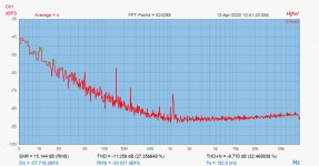
First graph is the output noise, under 60mA load current, 4,2V output, reference node bypassed by a 10uF 1206, X7r mlcc TDK capacitor. it's neither too small or a noname, its one of a better quality.
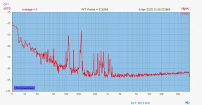
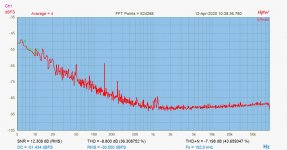
The second graph is the same, but I am shouting at it while registering. AAaaAaAAaaa... moderate loud. No vibration, direct mechanical effects. Purely acoustic coupling.
Just jumping in to say that under lockdown, I had some time to organize some measurements on regulators.
I see that here Tom and Hidjedewitje had discussed almost everything that is important about regs and their sharing the job with the dac under control.
I had observed some nice effects that had been mentioned, and I can see in my results.
Like these two graphs below. While measuring the regulator noise for a LT3045 modul executed by us, I had found something a bit weird. On having had a better look, I found this:
First graph is the output noise, under 60mA load current, 4,2V output, reference node bypassed by a 10uF 1206, X7r mlcc TDK capacitor. it's neither too small or a noname, its one of a better quality.
The second graph is the same, but I am shouting at it while registering. AAaaAaAAaaa... moderate loud. No vibration, direct mechanical effects. Purely acoustic coupling.
Attachments
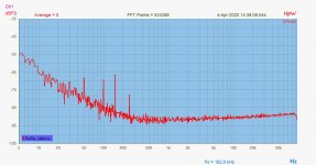
The setup is : the regulator capacitively coupled to Gerhard's low noise pre, (I see ~200pV/sqrtHz floor with input shorted) - 80dB gain applied - RTX6001 registering with 192kHz sampling, 96KHz bandwith.
The flat part of the spectrum is at 2nV/sqrtHz.
So, there is 80dB gain in the setup, the observed behaviour is not properly macroscopic, but at this level it's just a perfect microfon..If I touch, even slightly the setup - the signal just get crazy, goes ofc screen, saturates the ADC..
The flat part of the spectrum is at 2nV/sqrtHz.
So, there is 80dB gain in the setup, the observed behaviour is not properly macroscopic, but at this level it's just a perfect microfon..If I touch, even slightly the setup - the signal just get crazy, goes ofc screen, saturates the ADC..
The setup is : the regulator capacitively coupled to Gerhard's low noise pre, (I see ~200pV/sqrtHz floor with input shorted) - 80dB gain applied - RTX6001 registering with 192kHz sampling, 96KHz bandwith.
The flat part of the spectrum is at 2nV/sqrtHz.
So, there is 80dB gain in the setup, the observed behaviour is not properly macroscopic, but at this level it's just a perfect microfon..If I touch, even slightly the setup - the signal just get crazy, goes ofc screen, saturates the ADC..
The datasheet of the LT3042 states that ceramic capacitors can be microphonic. However the microphonics of the output capacitor should not be relevant as they are within the control loop of the LDO.
HOWEVER, the voltage over the reference resistor is guiding. If you have any deviation there, the regulator will try to put that deviation on the output, regardless on whether you like that or not.
Have you seen tried replacing the Vref cap with a film? C0G NP0 caps would also be appropriate, but they aren't available in uF sizes (not for reasonable prices at least).
It's good to see an indication of microphonics though!
Just done..☺
First pic: original config, with TDK 10uF mlcc.
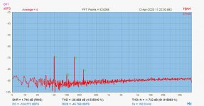
2nd pic: 2uF pana PPS
The spectra, twice, and me having a sore throat..
First pic: original config, with TDK 10uF mlcc.
2nd pic: 2uF pana PPS
The spectra, twice, and me having a sore throat..
Attachments
For clarity.. have just repeated the same test twice, given the 'slight ' inconsistency in the acoustic excitation signal.. ")
Two things can be seen: there is some residual breakthrough, but orders less.. there are MLCC coupling caps also in the pre, this could be one reason, but there is still a big MLCC output cap in the system, too..
Second: the low frequency noise corner has gone up, though less then it could be expected: it just shows that the 10uF nominal, zero bias value in the original MLCC bypass cap has decreased to ~ the half, at least..
There is no such thing with PPS
For clarity.. have just repeated the same test twice, given the 'slight ' inconsistency in the acoustic excitation signal..
Two things can be seen: there is some residual breakthrough, but orders less.. there are MLCC coupling caps also in the pre, this could be one reason, but there is still a big MLCC output cap in the system, too..
Second: the low frequency noise corner has gone up, though less then it could be expected: it just shows that the 10uF nominal, zero bias value in the original MLCC bypass cap has decreased to ~ the half, at least..
There is no such thing with PPS
Strange but interesting result. The noise level change has probably to do with the change in value. That's not the strange part. The strange part is that with the Film the peak at a little over 1kHz is much larger.
The 120Hz and 240Hz peaks are probably some rectified mains harmonics. I think these are coupled in somehow, because the LT3042 has really good performance at those frequencies.
Also, you might want to use a loudspeaker playing loud. It makes the test more consistent and more importantly, it saves you your voice
Yes, I should. By the way look back, i have just edited/ added also the baseline (60ohm, 1nV/sqrtHz) spectra, while shouting.. No change with respect to silence.
all the harmonics etc visible in the original are from 'me..'
The line harmonics You can see also in the baseline spectra.
So I have the feeling that also that 20uF MLCC on the output is contributing, and generating this residual.
all the harmonics etc visible in the original are from 'me..'
The line harmonics You can see also in the baseline spectra.
So I have the feeling that also that 20uF MLCC on the output is contributing, and generating this residual.
Last edited:
Yes, I should. By the way look back, i have just edited/ added also the baseline (60ohm, 1nV/sqrtHz) spectra, while shouting.. No change with respect to silence.
all the harmonics etc visible in the original are from 'me..'
The line harmonics You can see also in the baseline spectra.
So I have the feeling that also that 20uF MLCC on the output is contributing, and generating this residual.
It looks like the PSU noise is coming from the preamp. If you substract the preamp noise from the measurements, we can get a more accurate reading on the actual performance.
Keep the measurements coming!
Damn cookies. Thanks finally i succeed to download manuals.
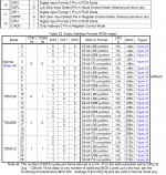
As far as i know ak4493 identify i2s input automaticly (pcm or dsd) and do its job. But in data sheet it forces me to choose input format for pcm. I just want 32bit/768Khz support thats all. Even in 32bit section there are 3 different variation
32-bit LSB justified
32-bit MSB justified
32-bit I2S compatible
i stuck please help me chose correct one.
Attachments

If you have not checked it please do:
Dual Mono AK4493 DAC (MK II) | Dimdim's Blog
There is a wealth of useful info there especially in the controller's code. If you're familiar with arduino you will get it quickly.
Dual Mono AK4493 DAC (MK II) | Dimdim's Blog
There is a wealth of useful info there especially in the controller's code. If you're familiar with arduino you will get it quickly.
If you have not checked it please do:
Dual Mono AK4493 DAC (MK II) | Dimdim's Blog
There is a wealth of useful info there especially in the controller's code. If you're familiar with arduino you will get it quickly.
Oh wow he updated his DAC to the 4493. I knew about his blog and his builds where quite helpfull.
His AK4490 design is much more elaborated though!
32-bit LSB justified
32-bit MSB justified
32-bit I2S compatible
i stuck please help me chose correct one.
Choose the one that matches your I2S source. For most USB boards that would be I2S format (also known as 'Philips I2S').
I2S - Wikipedia
Last edited:
Choose the one that matches your I2S source. For most USB boards that would be I2S format (also known as 'Philips I2S').
I2S - Wikipedia
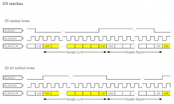
Please see attached my i2s source.
I can able to transmite data in STD as well as in Left justified format. I can also have a chance to tansmite 24 and 32 bit mode. But i am not sure which one is exact match in AK4493 side.
Attachments
Please see attached my i2s source.
I can able to transmite data in STD as well as in Left justified format. I can also have a chance to tansmite 24 and 32 bit mode. But i am not sure which one is exact match in AK4493 side.
I2S Compatible = STD = Philips I2S
Left Justified = LJ = LJ PCM
etc.
With LJ and Philips I2S it is commonly not necessary to specify 24 or 32 bits at the dac (receiver) end.
RJ format is different in that it is generally necessary to specify the number of bits (word size) for it to work properly.
Last edited:
- Home
- Source & Line
- Digital Line Level
- AK4493 DAC