Hello, given strict use of Opamps in the converter what you think should sound better (pro and cons) between:
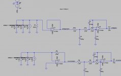
1) a classic IV converter with R in the feedback loop
2) R to ground followed by unity gain buffer
Only inverting the absolute phase?
The second has much higher input impedance but constant. Can be this a problem for the DAC? Do they really like low impedance?
Simulation gives same response at the end of the second op-amp, but different at the end of the first opamp.
DAC is a classic NOS multibit, like PCM56 with pure current output.
Attachments
Last edited:
Neither. Use transformers.
Also checkout Georgehifi's AD844 I/V idea:
Using the AD844 as an I/V
I tried it using four of them (dual TDA1541 balanced dac) and an OPA627 as a differential to single ended output stage but it suffered from HF oscillation so I went back to my transformer I/V.
Also checkout Georgehifi's AD844 I/V idea:
Using the AD844 as an I/V
I tried it using four of them (dual TDA1541 balanced dac) and an OPA627 as a differential to single ended output stage but it suffered from HF oscillation so I went back to my transformer I/V.
Look up the data sheet of your particular DAC. It will say what the max R to gnd is to avoid degradation of the sq.
1k you have is probably much too large. I've seen 100 ohms and lower.
Jan
Thanks! PCM56 datasheet only mention 1.2Kohm of output impedance..., but I have 3 in parallel...

What has "output impedance" got to do with it? The output impedance of a current source DAC should be very high.
Many current-output DAC chips have a fairly narrow range of output voltages they can cope with; go outside this range and you get distortion. If your chip is one of these then you may need to stick with the conventional 'virtual ground' opamp circuit.
Many current-output DAC chips have a fairly narrow range of output voltages they can cope with; go outside this range and you get distortion. If your chip is one of these then you may need to stick with the conventional 'virtual ground' opamp circuit.
Yes, the spec to look for is output common-mode range.
Hmmm. That PCM56 is basically a voltage-output DAC that can be configured for current output. No CM output spec. But with an output impedance of 1.2k, even with 100 ohm I/V the I-output, which is designed to stay very close to ground potential, will swing half a volt or so. Not a Good Thing!
Jan
Hmmm. That PCM56 is basically a voltage-output DAC that can be configured for current output. No CM output spec. But with an output impedance of 1.2k, even with 100 ohm I/V the I-output, which is designed to stay very close to ground potential, will swing half a volt or so. Not a Good Thing!
Jan
Last edited:
Thanks! PCM56 datasheet only mention 1.2Kohm of output impedance..., but I have 3 in parallel...
I suggest performing a search on this site for 'PCM56' and member 'Bernhard'. Bernhard probably has more implementation experience, and conducted more spectrum analyzer measurements on the PCM56 than most anyone else here. In addition to his measurements, you'll find his passive I/V circuit design (optimized for NOS operation), where the effective I/V resistance value @ D.C. is 100R.
Hello, given strict use of Opamps in the converter what you think should sound better (pro and cons) between:
1) a classic IV converter with R in the feedback loop
2) R to ground followed by unity gain buffer
I agree completely with abraxalito. In both your circuits, you make it very difficult for the op-amp: you require its output to produce a staircase-shaped waveform but it is not allowed to produce substantial slewing-induced distortion. It would become a lot easier with a bit of passive filtering before the op-amp or at least an RC parallel network in the classic IV converter.
Use the classic I/V (resistor in feedback loop) but place a CLC filter before the opamp. You'll need a matching resistor in series with the -ve input as termination for the filter. The CLC prevents the opamp going into slew-limiting and helps enormously with the SQ.
I've just seen a ROTEL scheme which is using a CRCR filter network between PCM and opamp.
Values are 10n-47ohm-10n-47ohm, hence just 100 ohm in serie.
I'll let you know if it sounds good and the measurements improve.
Google Image Result for https://www.wa2ise.com/subminiimages/rcd990an.jpg
Modifying CD player DAC circuits
I'm having that scheme in my Rotel RCD 990, with PCM63
I've just seen a ROTEL scheme which is using a CRCR filter network between PCM and opamp.
Values are 10n-47ohm-10n-47ohm, hence just 100 ohm in serie.
I'll let you know if it sounds good and the measurements improve.
Google Image Result for https://www.wa2ise.com/subminiimages/rcd990an.jpg
Modifying CD player DAC circuits
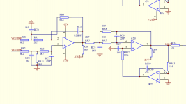
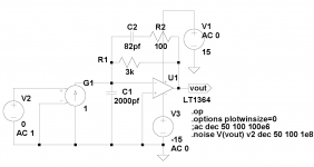
There is a third option
I did this back in the day of the AD1862. The op-amp and network forms a damped two pole network (~500kHz or so) but the big cap ends up taking the transients passively so the op-amp never has to slew. There is some noise gain but the OP's post filter would take that out. This requires a little thought and there is room to tweak the values for a particular amp.
I built this into a demo card, the HF hash removal from DAC clock noise was also dramatically reduced.
I agree completely with abraxalito. In both your circuits, you make it very difficult for the op-amp: you require its output to produce a staircase-shaped waveform but it is not allowed to produce substantial slewing-induced distortion. It would become a lot easier with a bit of passive filtering before the op-amp or at least an RC parallel network in the classic IV converter.
I did this back in the day of the AD1862. The op-amp and network forms a damped two pole network (~500kHz or so) but the big cap ends up taking the transients passively so the op-amp never has to slew. There is some noise gain but the OP's post filter would take that out. This requires a little thought and there is room to tweak the values for a particular amp.
I built this into a demo card, the HF hash removal from DAC clock noise was also dramatically reduced.
Attachments
I did this back in the day of the AD1862. The op-amp and network forms a damped two pole network (~500kHz or so) but the big cap ends up taking the transients passively so the op-amp never has to slew. There is some noise gain but the OP's post filter would take that out. This requires a little thought and there is room to tweak the values for a particular amp.
I built this into a demo card, the HF hash removal from DAC clock noise was also dramatically reduced.
Scott, as I see this, it only works with bipolar signals, right? Else the cap gets charged with the average DC.
Some DACs have unipolar output signals and the cap has to be returned to the supply mid-point (which often is available at a pin of the chip).
Jan
Website of Wayne Stegall - Managing TIM contains very useful information on opamps in I/V-Application, avoiding TIM issues. We find a solution similar very to what ScottW has posted plus an enhancement to it which eases component value calculation and which makes things a bit more predictible in general.
Last edited:
Scott, as I see this, it only works with bipolar signals, right? Else the cap gets charged with the average DC.
Some DACs have unipolar output signals and the cap has to be returned to the supply mid-point (which often is available at a pin of the chip).
Jan
??? Doesn't matter it looks like an ordinary 3K transresistance I to V.
Website of Wayne Stegall - Managing TIM contains very useful information on opamps in I/V-Application, avoiding TIM issues. We find a solution similar very to what ScottW has posted plus an enhancement to it which eases component value calculation and which makes things a bit more predictible in general.
Yes the "original" appeared on the AD797 datasheet (1992) I say original in quotes because it's standard photo diode I to V theory. Wayne is an interesting guy (his non-audio stuff is a hoot) but beware he does not discuss the noise gain issues. I should have embellished the application on the data sheet but so it goes, if anyone wants to try it I am always around to help.
- Status
- This old topic is closed. If you want to reopen this topic, contact a moderator using the "Report Post" button.
- Home
- Source & Line
- Digital Line Level
- IV Opamp converter after DAC: which of the two circuits?