I have DIYed my digital system since 90'. There was no choice but multibit like pcm1704 those days because I couldn't remember DSM DACs out there. Since then my preference is multibit until now. But the world has changed to DSM and pcm1704 is completely obsolete. I need some replacement with pcm1704 though I don't have enough time to listen to music like the young. That's why DSM wasn't the target for listening purpose in the first place. I intended to design DSM DAC for measurement purpose because it has excellent THD performance. It's not difficult to implement DSM into FPGA(I have much experience about designing FPGA as an engineer), where enough resources are available at a reasonable cost. My solution is to use high-speed DAC and FPGA from scratch. Commercial DAC chips can't make me happy. The top priority was multibit and the second was DSM. It took about one year to fix both functions. Time is on my side now. No delivery time exists for me.
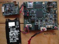
The first pic is the PCB. A small one is a pcm1792 for reference. This is useful to verify my design whether it's correct or not. OLED is also cost-effective and necessary human interface. The board can read SDmicro in exFAT with the 32Mbyte cluster. SD isn't mandatory for my setup because music files are usually sent by a transport through an optical cable. SD is useful to update the firmware of FPGA and ARM controller. I want to upgrade my transport to be capable of exFAT. This is a prototype of exFAT for me. FPGA is spartan xc6slx25 in 256BGA. I don't want to use BGA because it means hand soldering is entirely impossible, and outsourcing is costly. The physical law forces me to use BGA which can guarantee high-speed signal processing and many available pads. No way besides BGA in recent technology.
A DAC chip is AD9717(14bit linear up to 125MSPS). If your target is DSM, at least 50MSPS is necessary. High-speed DACs for RF have inevitably no glitch, i.e., LTC2642(1MSPS) is 500pV-s while a little bit old model DAC2904(125MSPS) is 2pV-s. A massive glitch in RF DACs means nonsense. Pcm1704, which is the only glitch-free audio device, probably such level. Recent ones like AD9717 have no data about a glitch. In other words, there is none. Another significant advantage is output compliance voltage. AD9717 is from +1.2V to -0.5V. So, it's very easy to have +0.75V to 0V. You can have a 3Vpp differential output(6Vpp at SE) by the 6dB amplifier. It means passive I/V is available by one register which has completely no degradation when you parallel current source to improve THD, noise power, and temperature stability. I can't imagine active I/V which operates successfully in both large current and high frequency used in DSM. The datasheet of ADA4898 says THD performance is measured at +1mA to -1mA. I know large current can degrade THD.
The fatal factor to have excellent THD in DSM is relative accuracy between every resolution, i.e., 10001 to 10010... 00000 to 00001,00001 to 00010... 01110 to 01111 in the 5bit quantizer. Rough estimation from my experience, you need at least 1ppm accuracy for 120dB THD. This isn't a practical number in a normal situation. Temperature drift is probably the first destroyer to disturb stability. Paralleling current sources and on-demand calibration are the weapon against an attacker. However, 1ppm accuracy isn't an imaginary number by the simple digital process as long as the temperature is stable. Two steps are mandatory. One is the internal calibration of AD9717, which can adjust the difference between its 32 banks. AD9717(16384resolution) has thirty-two 512resolution DACs. The input signal across the border between banks ends up distortion. The effort to try to adjust the difference is sometimes successful and sometimes useless. The first step is to select a good combination manually. If you do paralleling four current sources, you have a chance of a more successful result than two current sources because there are many combinations to be tried.
The second one is 6bit PWM by FPGA. Sixbit PWM can have 64 values to do fine adjust. Fifteen-bit linear and 6bit PWM or sixteen-bit linear and 5bit PWM are the candidates. The former is better than the latter from my experience. If your DSM is 5bit quantizer, 31 resolutions have their own PWM word(one word is 6bit). You need to manually calibrate them to see if what values can decrease the 2nd and the 3rd harmonic. It takes about 5 minutes to do a manual calibration. If you can tame a micro to do the job, it takes about 10 seconds. This is reasonable for on-demand calibration. Five minutes for experienced human calibrator like me is a little bit heavy duty to call it as on-demand. The internal calibration data done by AD9717 and manually adjusted data are digital, which means they can be stored and loaded to have the same result after power off and on.
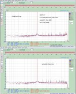
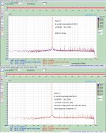
The 2nd pic is THD and S/N relative to the fundamental. X256OSR is better than x64. If you measure THD just after the calibration, 120dB isn't particular value. If you do paralleling eight current sources(4x8=32mA), 120dB is a normal one. The 3rd pic is the comparison between four and eight. S/N is irrelevant to THD value. X256OSR can achieve more than 110dB in 20kHz bandwidth without A-filter. More than 110dB S/N with 120dB THD isn't an easy task. The topology by RF DAC has the best value at the maximum amplitude. SFDR is usually 130dB when the amplitude is above 30dBFS. That's why the larger the amplitude, the better THD, and S/N. If you want -10dBFS amplitude, a passive divider by a register is superior to digital pot.
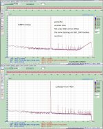
The 4th pic is THD of pcm1792. The input is 1bit DSM (DSD) from FPGA. It has an excellent result in x64OSR in spite of one current source. I/V is ADA4898 and the same circuit as the datasheet. But in x256OSR, THD loses a successful result. Noise power can maintain the performance. I would say this is because of large current and high frequency or inaccuracy in internal analog FIR LPF. If you consider it, paralleling in pcm1792 totally can't be a good solution. I'm sure passive I/V is superior to active one when you do paralleling. Commercial audio DACs also must have large compliance voltage to utilize their multiple current sources without degradation, IMHO.
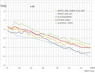
The 5th pic is a rough comparison of THD between DACs I ever have used. An old-school pcm1704_K isn't high score. The advantage of pcm1704 is glitch-free, no need to have a digital process to output -120dBFS and have an excellent number below -70dBFS. LTC2642 is a modern one with 16bit monotonicity. But it doesn't have the same sound as pcm1704. I prefer pcm1704 to LTC2642 though it has a better number. AD9717 in multi-bit(14bit linear and 2nd DSM) has almost the same value as LTC2642. Internal calibration makes the chip accurate as 16bit resolution. Fourteen-bit is superior to 16bit at small amplitude. This is the inherent nature of DSM(it begins to act as DSM at small amplitude) because relative accuracy of 14bit is better than 16bit. AD9717 in 5bitDSM is excellent. But R-ch isn't good as L-ch. If you re-calibrate R-ch, there is a chance to be a better number.
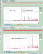
The 6th pic is THD and IMD of AD9717 in multibit. It means internal calibration only. L-ch is worse than R-ch. If you do re-calibration, you can have the same result as R-ch in 20 trials. Internal calibration is done by ARM. It takes about 1 second to finish. X256OSR and x512OSR(the maximum OSR) have almost the same value in multibit. In 5bitDSM, x256OSR is a little bit better than x512OSR in THD. S/N is nearly the same.
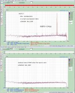
The 7th is IMD of AD9717 in 5bitDSM. The same hardware can have another result. Less resolution with high accuracy(DSM) outperforms high resolution with low accuracy(multibit). Digital processing by FPGA can make DSM available. I need to upgrade my system to be compatible with the AD9717. But It means to populate 8 DACs to listen real sound. It takes three months.")
I originally intended to swing by DSM but went into orbit around DSM for several months. So, my journey to generic pcm1704 is still on the way.
The first pic is the PCB. A small one is a pcm1792 for reference. This is useful to verify my design whether it's correct or not. OLED is also cost-effective and necessary human interface. The board can read SDmicro in exFAT with the 32Mbyte cluster. SD isn't mandatory for my setup because music files are usually sent by a transport through an optical cable. SD is useful to update the firmware of FPGA and ARM controller. I want to upgrade my transport to be capable of exFAT. This is a prototype of exFAT for me. FPGA is spartan xc6slx25 in 256BGA. I don't want to use BGA because it means hand soldering is entirely impossible, and outsourcing is costly. The physical law forces me to use BGA which can guarantee high-speed signal processing and many available pads. No way besides BGA in recent technology.
A DAC chip is AD9717(14bit linear up to 125MSPS). If your target is DSM, at least 50MSPS is necessary. High-speed DACs for RF have inevitably no glitch, i.e., LTC2642(1MSPS) is 500pV-s while a little bit old model DAC2904(125MSPS) is 2pV-s. A massive glitch in RF DACs means nonsense. Pcm1704, which is the only glitch-free audio device, probably such level. Recent ones like AD9717 have no data about a glitch. In other words, there is none. Another significant advantage is output compliance voltage. AD9717 is from +1.2V to -0.5V. So, it's very easy to have +0.75V to 0V. You can have a 3Vpp differential output(6Vpp at SE) by the 6dB amplifier. It means passive I/V is available by one register which has completely no degradation when you parallel current source to improve THD, noise power, and temperature stability. I can't imagine active I/V which operates successfully in both large current and high frequency used in DSM. The datasheet of ADA4898 says THD performance is measured at +1mA to -1mA. I know large current can degrade THD.
The fatal factor to have excellent THD in DSM is relative accuracy between every resolution, i.e., 10001 to 10010... 00000 to 00001,00001 to 00010... 01110 to 01111 in the 5bit quantizer. Rough estimation from my experience, you need at least 1ppm accuracy for 120dB THD. This isn't a practical number in a normal situation. Temperature drift is probably the first destroyer to disturb stability. Paralleling current sources and on-demand calibration are the weapon against an attacker. However, 1ppm accuracy isn't an imaginary number by the simple digital process as long as the temperature is stable. Two steps are mandatory. One is the internal calibration of AD9717, which can adjust the difference between its 32 banks. AD9717(16384resolution) has thirty-two 512resolution DACs. The input signal across the border between banks ends up distortion. The effort to try to adjust the difference is sometimes successful and sometimes useless. The first step is to select a good combination manually. If you do paralleling four current sources, you have a chance of a more successful result than two current sources because there are many combinations to be tried.
The second one is 6bit PWM by FPGA. Sixbit PWM can have 64 values to do fine adjust. Fifteen-bit linear and 6bit PWM or sixteen-bit linear and 5bit PWM are the candidates. The former is better than the latter from my experience. If your DSM is 5bit quantizer, 31 resolutions have their own PWM word(one word is 6bit). You need to manually calibrate them to see if what values can decrease the 2nd and the 3rd harmonic. It takes about 5 minutes to do a manual calibration. If you can tame a micro to do the job, it takes about 10 seconds. This is reasonable for on-demand calibration. Five minutes for experienced human calibrator like me is a little bit heavy duty to call it as on-demand. The internal calibration data done by AD9717 and manually adjusted data are digital, which means they can be stored and loaded to have the same result after power off and on.
The 2nd pic is THD and S/N relative to the fundamental. X256OSR is better than x64. If you measure THD just after the calibration, 120dB isn't particular value. If you do paralleling eight current sources(4x8=32mA), 120dB is a normal one. The 3rd pic is the comparison between four and eight. S/N is irrelevant to THD value. X256OSR can achieve more than 110dB in 20kHz bandwidth without A-filter. More than 110dB S/N with 120dB THD isn't an easy task. The topology by RF DAC has the best value at the maximum amplitude. SFDR is usually 130dB when the amplitude is above 30dBFS. That's why the larger the amplitude, the better THD, and S/N. If you want -10dBFS amplitude, a passive divider by a register is superior to digital pot.
The 4th pic is THD of pcm1792. The input is 1bit DSM (DSD) from FPGA. It has an excellent result in x64OSR in spite of one current source. I/V is ADA4898 and the same circuit as the datasheet. But in x256OSR, THD loses a successful result. Noise power can maintain the performance. I would say this is because of large current and high frequency or inaccuracy in internal analog FIR LPF. If you consider it, paralleling in pcm1792 totally can't be a good solution. I'm sure passive I/V is superior to active one when you do paralleling. Commercial audio DACs also must have large compliance voltage to utilize their multiple current sources without degradation, IMHO.
The 5th pic is a rough comparison of THD between DACs I ever have used. An old-school pcm1704_K isn't high score. The advantage of pcm1704 is glitch-free, no need to have a digital process to output -120dBFS and have an excellent number below -70dBFS. LTC2642 is a modern one with 16bit monotonicity. But it doesn't have the same sound as pcm1704. I prefer pcm1704 to LTC2642 though it has a better number. AD9717 in multi-bit(14bit linear and 2nd DSM) has almost the same value as LTC2642. Internal calibration makes the chip accurate as 16bit resolution. Fourteen-bit is superior to 16bit at small amplitude. This is the inherent nature of DSM(it begins to act as DSM at small amplitude) because relative accuracy of 14bit is better than 16bit. AD9717 in 5bitDSM is excellent. But R-ch isn't good as L-ch. If you re-calibrate R-ch, there is a chance to be a better number.
The 6th pic is THD and IMD of AD9717 in multibit. It means internal calibration only. L-ch is worse than R-ch. If you do re-calibration, you can have the same result as R-ch in 20 trials. Internal calibration is done by ARM. It takes about 1 second to finish. X256OSR and x512OSR(the maximum OSR) have almost the same value in multibit. In 5bitDSM, x256OSR is a little bit better than x512OSR in THD. S/N is nearly the same.
The 7th is IMD of AD9717 in 5bitDSM. The same hardware can have another result. Less resolution with high accuracy(DSM) outperforms high resolution with low accuracy(multibit). Digital processing by FPGA can make DSM available. I need to upgrade my system to be compatible with the AD9717. But It means to populate 8 DACs to listen real sound. It takes three months.
I originally intended to swing by DSM but went into orbit around DSM for several months. So, my journey to generic pcm1704 is still on the way.
Attachments
As very interesting post/build but no response yet, may be it is much technical thus not easy to understand... Then I have some questions to digest your post.
Today's typical audio DACs uses non 1bit SDM and dynamic element matching (DEM), contrary to them, if I understood correctly, your DAC uses upper 5 or 6 bits of true multibit DAC and calibrate them precisely thus eliminating DEM, is this understanding right?
About external calibration, the 6bit PWM uses 14th bit of AD9717? If this is correct, at least 19bit accuracy is achievable, is my understanding. But 6bit PWM uses 64 or more clock period, and before PWM, DSM uses 64 to 256 times OSR therefore 64*64 4096 OSR is needed. 48kSPS audio and 4096 OSR result 200MSPS which is over 125MSPS. This must be something misunderstanding so please point out my mistake.
Another question, If gentle DSM rounding and linear upper 13bits is used, rest 14th bit can be used external calibration?
Yes, your understanding and calculation are correct. The word PWM I used didn't have an exact technical meaning. When I started to design this topology, I used linear(multibit) 16bit DAC chip and 4bit true PWM. You can have up to 128OSR in this situation because of 48k*128*16=98.304MHz. It worked well as I thought. True 20bit resolution is so accurate that DSM operates successfully like SIM in the digital domain. You can eliminate DEM by external calibration.
Then I modified true PWM to be quasi PWM, which is the same one as I wrote before. Quasi PWM means DSM like one. Sampling data used in DSM must be some group. Single data doesn't have meaning, i.e., single data in 1bit-DSM(DSD) is 0 or 1, which have much difference from the original one. After averaging some data, their values become meaningful. The averaging is the key to output 20bit resolution in 1bitDSM. So is PWM. Averaging like DSM is also applicable to PWM.
You don't need to do PWM within a single sampling point. If you want to output 0x00008(20bit resolution) in linear 16bit and true 4bitPWM, eight 0x0000 and eight 0x0001 are necessary, which means 0x00008 in single sampling point. If you do quasi PWM, eight 0x0000 and eight 0x0001 are the same as true PWM. But they are not in a single sampling point, but in 16 sampling points like DSM which needs some sampling points to represent their true(audible) value.
If you do quasi PWM, the sampling frequency you need is a multiplication of OSR. The disadvantage of quasi PWM is how long duration is acceptable. Four-bit quasi PWM requires at least 16 points. Because of the inherent nature of DSM, "spreading of PWM" is usually less than 16*3 in 4bitPWM. You also need to memorize how many points are used. If your DSM is 5bit, you must have 31 counters to store and load the value.
But you need at least linear 14bit to have a successful result. If your linear DAC is 12bit, you need to have 8bit quasi PWM. It means too much spreading and ends up distortion in the audio band. That's why linear 14bit & quasi 6bitPWM,15bit & quasi 6bitPWM, and 16bit & quasi 5bitPWM are the candidates. From my experience, linear 15bit & quasi 6bitPWM is the best.
Thank you xx3stksm. I understood your quasi PWM, that is not mandatory to make up the binary pulse width in one period, like DEM (or fractional PLL?), it does not correct every error in a sample. How divide or distribute and align the correction binary to samples may be secret know how or mathematically simulated but I don't have skills what it takes.
Could you sketch what you exactly mean by quasi-PWM?
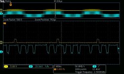
If your linear DAC is 15bit and 6bit quasi-PWM in 5bitDSM, one step in DSM is 0x0400. Below -24dBFS, 5bitDSM can use only three values, 0x7c00(-1 in 5bit),0x0000(0) and 0x0400(1). Blue in the upper window shows raw output (without analog filter) of DAC. It has only three values. Yellow means a digital pulse of quasi-PWM. If it is 0, no addition occurs, which means the output(1) is 0x0400. If it is 1, the output(1) becomes 0x0400+1=0x0401. Ten out of 11 are probably 0x0400, and one out of 11 is 0x0401 from the pic. So, the first pulse can be equivalent to 0x0400+(1/11). Next one is 0x0800+(1/10). I guess total quasi-PWM value is 6/64.
This is in x256OSR. One actual cycle time to complete 6bit quasi-PWM is about 8.4(2.8*3)micro sec. The minimum value in x256OSR is (1/12.288)*64=5.2micro sec. However, 5.2micro sec never occurs in high order DSM because it ends up successive sixteen-four 1s. One cycle is relatively short in this case because the zoomed area has many 1s. A negative value(-1) also has the same topology. But a digital pulse for a negative one is excluded to avoid complexity.
Attachments
How divide or distribute and align the correction binary to samples may be secret know how or mathematically simulated but I don't have skills what it takes.
DSM architecture in the digital domain is relatively simple but needs incredible accuracy, i.e, linear 15bit and 6bit quasi-PWM(fine tuning). You don't need to have a special technique. What you need is coarse registers and fine registers. My FM is applicable up to 6bit quasi-PWM, where you have 64 registers each. Level 0 in 5bitDSM is 0x0000, level 1 is 0x0400...,level 15 is 0x3c00, and level -15 is 0x4800.
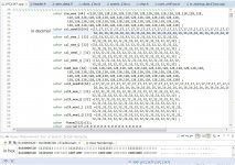
But calibrated value for level 1 isn't 0x0400 because linear 15bit DAC has an error. Coarse registers(from -15 to +15) are for the purpose. The upper window in the pic is default values of such registers. cal_memX16[64](line 34&35) is coarse ones for L ch. The lower window is after calibration. If linear DAC has a perfect accuracy, the upper and the lower(in hex) have the same value. The second data(coarse byte for level -2) in the lower window is 0x13. The default one is 0x11. So, the actual value for level -2 is 0x7000+(0x13-0x11)=0x7002. dsm_mem[64](line30 to line33) is fine registers for L ch. The fine registers, which means a fraction, are also modified at calibration. Both can adjust the error of linear DAC as close as possible. If you can have a perfect accuracy, more than 120dB THD is achievable.
Attachments
So if I understand it correctly, you have a digital sigma-delta with 5-bit quantizer driving a 15-bit DAC. If the DAC were ideal, its lower 10 bits could simply be 0 at all times, but of course it is not ideal.
To correct for the error of the DAC, you don't use multiples of 1024 but instead you use slightly different codes. Calibration data stored in a memory tells the FPGA what codes to send to the DAC.
However, you would like to make calibration steps smaller than one LSB of the 15-bit DAC. To achieve that you switch between codes such that the average value is correct. This is what you call quasi-PWM.
Today's typical audio DACs uses non 1bit SDM and dynamic element matching (DEM), contrary to them, if I understood correctly, your DAC uses upper 5 or 6 bits of true multibit DAC and calibrate them precisely thus eliminating DEM, is this understanding right?
The usual DEM techniques such as data-weighted averaging and many improved variants of it are not usable because they require that all unit elements are used for converting each code.
For example, suppose you have a three-bit DAC with seven unit current sources (some of these algorithms actually require eight or nine sources for three bits, but that's a detail). If you had to convert the number 3, you could first use units 1, 2 and 3, the next time use 4, 5 and 6, then 7, 1 and 2 and so on. The average current that comes out of the DAC when the code is 3 then automatically becomes 3 times the average of the values of all seven unit current sources.
Unfortunately normal DAC chips like the AD9717 always use the same current sources for the same code, so you can't apply tricks like this.
However, you would like to make calibration steps smaller than one LSB of the 15-bit DAC. To achieve that you switch between codes such that the average value is correct. This is what you call quasi-PWM.
Thank you for your elaboration.
DSM theory is now almost completed in the digital domain. You can see how to implement optimum DSM from here. PlayPcmWin / Wiki / PCMtoSDM
This is a convenient explanation and easy to go. However, multibit DSM requires high accuracy to have an ideal implementation in the analog domain. DEM is one of the effective ways to achieve such accuracy though it's impossible for a DIYer to do.
A possible way for a DIYer is quasi PWM, where you can have a fraction (n/64) for necessary accuracy. Linear 14bit and 6bit quasi PWM isn't enough. Linear 15bit and 6bit quasi PWM is probably most useful. Linear 16bit and 6bit quasi PWM is overkill from my experience.
This is a little bit off topic.
My intention to do a calibration on DAC is to make "complimentary" DAC with ADC like NPN and PNP. I don't think 120dB THD has meaning for good SQ. Even 100dB is overkill. But if I want to verify whether my DSM is optimum or not, 120dB THD is the target. AFAIK, it's very difficult for ADC chip to have such number. I have DIYed ADC(AD7960) board which manages to have 120dB THD. But two ADC boards can't have the same result with the same input. In other words, they can't have absolute accuracy but can have only a relative one.
I used to select a transistor for a better complimentary pair. I needed relative accuracy. So are DAC and ADC. As long as my ADC isn't perfect, DAC must be selected(calibrated) to be a better complimentary. I don't know complimentary DAC and ADC is meaningful. I can't calibrate my ADC though I know there is a man who is capable to calibrate ADC in this forum. My calibration is only for DAC but is some help to measure 120dB THD.
- Status
- This old topic is closed. If you want to reopen this topic, contact a moderator using the "Report Post" button.
- Home
- Source & Line
- Digital Line Level
- Two way DAC(multibit and DSM)from scratch with input options(SDmicro,toslink and IIS)