Hi, what does it happen if I negate (invert) "sdata" from pin 26 of CS8412 to DAC?
I'm using CS8412 in Mode 5 (5 - Out, L/R, 16 Bits LSBJ) with PCM56.
I'm asking this because by inverting SDATA, J-test Jitter is much better, but I'm worrying to have lost the LSB. Or not?
I also prefer the sound by inverting SDATA, but no scheme is inverting it. So, what's happening?
Simulation unfortunately this time doesn’t help.
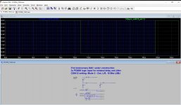
Attachments
Last edited:
Hi, what does it happen if I negate (invert) "sdata" from pin 26 of CS8412 to DAC?
I'm using CS8412 in Mode 5 (5 - Out, L/R, 16 Bits LSBJ) with PCM56.
I'm asking this because by inverting SDATA, J-test Jitter is much better, but I'm worrying to have lost the LSB. Or not?
I also prefer the sound by inverting SDATA, but no scheme is inverting it. So, what's happening?
Simulation unfortunately this time doesn’t help.
Performing a simple logic inversion of the sdata stream will produce a DAC chip analog waveform phase inversion plus an 1 LSB D.C. offset. I can't offer a ready guess for why a jitter test should be significantly affected.
Performing a simple logic inversion of the sdata stream will produce a DAC chip analog waveform phase inversion plus an 1 LSB D.C. offset. I can't offer a ready guess for why a jitter test should be significantly affected.
If the jitter measurement includes what the LSB is doing, when the data is inverted, the LSB doesn't change (or as often) so the jitter will appear reduced?
If the jitter measurement includes what the LSB is doing, when the data is inverted, the LSB doesn't change (or as often) so the jitter will appear reduced?
That sounds plausible. I seem to recall that a J-test toggles the LSB at something like a 229Hz rate to generate close-in jitter sidebands.
Now that I think about it a little more, the digital bipolar zero crossing would be dramatically affected. The digital bipolar zero crossing produces the greatest change of bit states for many multi-bit quantizer type DACs (R-2R, etc.) and so, produces the greatest jitter. Hence the LSB toggling of the J-test, I suppose.
Last edited:
Nothing happens. It just gets inverted.
Correct only if it is a true 2's complement data inversion, which requires an binary adder unit. A simple logic inversion of the data will leave a 1 LSB offset.
There is no offset. A one becomes zero and a zero becomes one.
[sigh]
There is no offset. A one becomes zero and a zero becomes one.
When you invert 16-bit two's complement data:
1111111111111110 (two's complement for -2) becomes 0000000000000001 (two's complement for +1)
1111111111111111 (two's complement for -1) becomes 0000000000000000 (two's complement for 0)
0000000000000000 (two's complement for 0) becomes 1111111111111111 (two's complement for -1)
0000000000000001 (two's complement for +1) becomes 1111111111111110 (two's complement for -2)
and so on. So clearly there is a sign inversion and a -1 LSB offset.
The number of switching bits stays exactly the same though, so I have no idea why this should affect a jitter measurement.
Guess that would be the inverter.So clearly there is a sign inversion
At least you haven't called it dc.and a -1 LSB offset.
- Status
- This old topic is closed. If you want to reopen this topic, contact a moderator using the "Report Post" button.
- Home
- Source & Line
- Digital Line Level
- Invert "sdata" from pin 26 of CS8412