so i just got done building DDNF as described here and am very impressed with the sound.
https://www.diyaudio.com/archive/blogs/dvb-projekt/attachments/399d1305647776-pedja-rogic-s-discrete-diamond-non-feedback-i-v-stage-out-production-pedja-rogic-ddnf-iv-stage.pdf
in the document he's talking about adding ccs, and i'd like to know what else that can be done to this to improve the performance.
The absolute values of the LC network aren't so important but the ratios define the filter characteristic so must be fairly tightly controlled.
I'm using 680uH and 470uH in my lingDAC filter but I've experimented with inductors down to 22uH or so and above 1mH. You can find the schematic in post#36 in this thread : lingDAC - cost effective RBCD multibit DAC design
If you don't want to go as far as two Ls and five sets of Cs you can just try with one L and two sets of Cs.
Glad you're a happy TDA1387 customer")
Just a thought - Pedja's schematic looks to be designed for bi-directional current input (as would be gotten from a '1541A) but for TDA1387 you only need single direction current input. So SE style is much better suited.
I'm using 680uH and 470uH in my lingDAC filter but I've experimented with inductors down to 22uH or so and above 1mH. You can find the schematic in post#36 in this thread : lingDAC - cost effective RBCD multibit DAC design
If you don't want to go as far as two Ls and five sets of Cs you can just try with one L and two sets of Cs.
Glad you're a happy TDA1387 customer
Just a thought - Pedja's schematic looks to be designed for bi-directional current input (as would be gotten from a '1541A) but for TDA1387 you only need single direction current input. So SE style is much better suited.
Last edited:
thank you again, richard. you're an inspiration to us all.
does it make sense to put LC filter after the I/v if im putting one before?
and i also want to try an LC filter without the droop correction and was looking at the one used in old AudioNote dacs and also Dac End 2 by quinghao. the values were 120uh and 0.01uf. im thinking they're shooting for 20khz lpf?
Yes certainly it can make sense to put another LC filter after the I/V - I'm doing that on my 3rd generation lingDAC I've put the droop correction into the 2nd filter.
Do you have a link for those filters? The component values don't sound right to me for 20kHz. With 100uH I find I need capacitors much bigger than 10nF.
I've put the droop correction into the 2nd filter.Do you have a link for those filters? The component values don't sound right to me for 20kHz. With 100uH I find I need capacitors much bigger than 10nF.
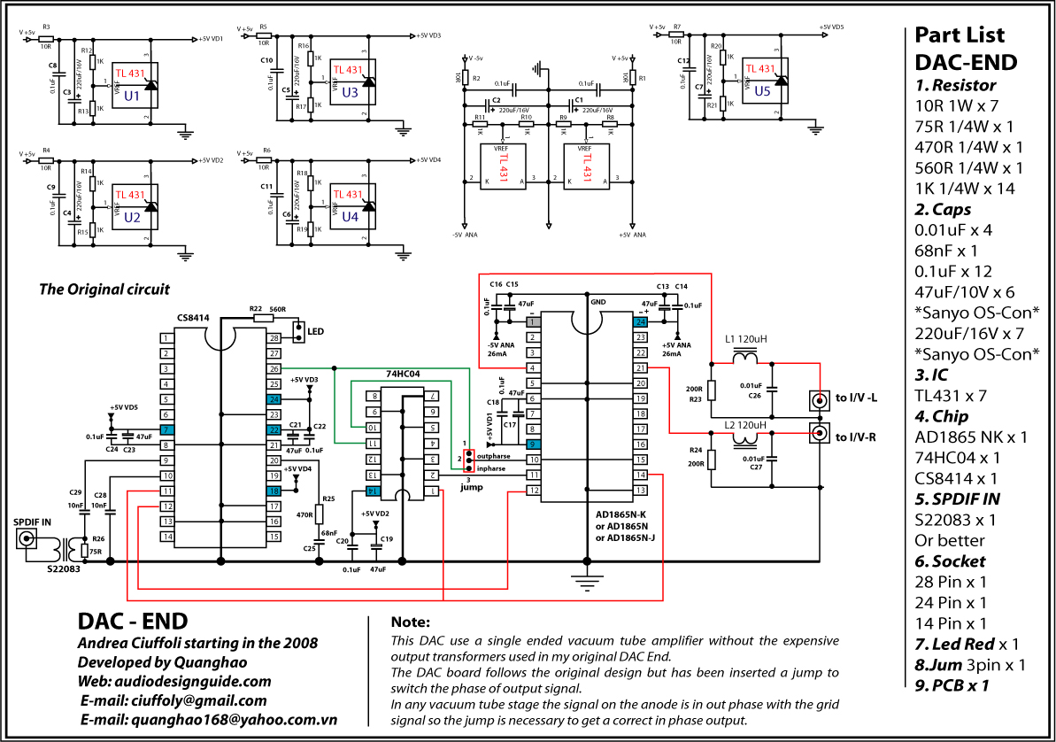
this is the only one i can find atm.
lingDAC sounds amazing, btw. the inverter in your DAC, 'U7', i'm reading that it not only inverts data signal but also limits all other signals? what benefit would this have on 1387 and is the limitation amount specific to 1387 or can i use it with 1543 with the same benefit?
Last edited:
Ah thanks for posting that schematic, I see what they're doing differently from me.
They first do I/V conversion with a resistor (can't see very clearly but looks 200R) then after that they do filtering with the LC. So the signal's become a voltage prior to filtering. With my lingDAC I keep the DAC's output signal as a current while filtering, only later do I convert to a voltage. I'm not a fan of passive I/V any more, it makes the DAC far too power supply sensitive.
The inverter in lingDAC is powered from a 2.5V shunt reg (TL431) so yes it limits the output logic '1' voltage to the DAC to 2.5V. I didn't want to have the potential for noise on the digital signals to couple via the DAC so I opted to buffer (or invert) them all. Certainly you can use the same with the TDA1543.
The inverter in lingDAC is powered from a 2.5V shunt reg (TL431) so yes it limits the output logic '1' voltage to the DAC to 2.5V. I didn't want to have the potential for noise on the digital signals to couple via the DAC so I opted to buffer (or invert) them all. Certainly you can use the same with the TDA1543.
ah, i understand now! very clever! i will try this with my dac on a vero board. thank you again.
To have it run hotter, reduce the right-most 1k resistors in the diamond - try 680R.
74HC86 is most certainly available in 14pin DIL - SN74HC86N Texas Instruments | Integrated Circuits (ICs) | DigiKey
74HC86 is most certainly available in 14pin DIL - SN74HC86N Texas Instruments | Integrated Circuits (ICs) | DigiKey
can i also make the resistors top and bottom a little different value for a bit of asymmetry?
i really like the sound of this i/v, it's perhaps the best i've ever come across in terms of fidelity but it sounds little too 'hifi' and cold to my liking. im trying to inject a little bit of 2nd order harmonics into it and think tweaking with the resistors a bit might do the trick.
i really like the sound of this i/v, it's perhaps the best i've ever come across in terms of fidelity but it sounds little too 'hifi' and cold to my liking. im trying to inject a little bit of 2nd order harmonics into it and think tweaking with the resistors a bit might do the trick.
Hi all,
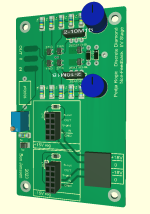
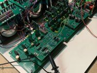
Planning to build the Pedja's DDNF as well.
I've added the CCS's in combination with CRD's.
Current throught all bjt's is between 4 and 5,5mA.
This IV stage will be used for a TDA1541A DAC: https://www.diyaudio.com/community/...ac-using-tda1541a.79452/page-411#post-7403416
PSU are pre-regulated Jung-Didden supperreg's. These will be put in the female 2x5 headers on the PCB.
What do you think? Any concern's or advice?
Attachments
Hello,
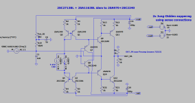
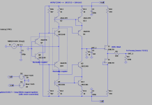
Been playing in real life and spice with the standard Pedja Rogic DDNF, the one in the previous post and the one posted below. This one (below) seems most stable in bias drift during temperature changes and give nicest harmonic profile. Also, I can use some dual bipolars for the current mirror, have plenty in stock and never been able to use them with a good purpose.
Bias is about 2.5mA in the output stage. I'm wondering if an additional buffer stage running on higher bias is needed to drive my preamp, connected with 50cm shielded RCA cables. Input resistance of my preamp is +-20kOhm (input resistance of Muses 72323).
Now back to the drawing board, to design PCB's.
Attachments
Last edited:
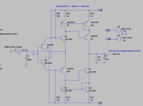
Finalized the design.
I added a single ended Jfet buffer using 10mA IDSS 2SK170BL's.
Prototype is running and output offset is less than 1mV.
Below circuit is the AS-BUILD circuit.
I noticed the 1,8nF cap on the output of the IV-stage and before the buffer is a MUST have when playing music and probing output with the scope.
PCB is ready to be send to manufacturer.
Attachments
- Home
- Source & Line
- Digital Line Level
- tweaking pedja's Diamond differential I/V