I'll need to order some more chips some time soon, we just have to take our chances ") I haven't so far found any chips I suspect to be fakes but not every single chip works perfectly. I always check pin7 voltage with just power (pin4/5) connected - this weeds out many faulty chips (but not all).
I haven't so far found any chips I suspect to be fakes but not every single chip works perfectly. I always check pin7 voltage with just power (pin4/5) connected - this weeds out many faulty chips (but not all).
I haven't so far found any chips I suspect to be fakes but not every single chip works perfectly. I always check pin7 voltage with just power (pin4/5) connected - this weeds out many faulty chips (but not all).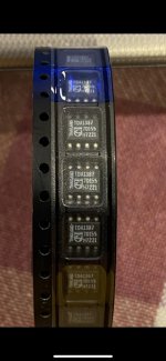
They don't look dissimilar to the ones I have, looking promising.
Yes, been building up more Kubeliks and trying them out with different opamps. Also making measurements of stuff like peak output level (a iittle too low for some reason, needing investigation) and DC offsets. So far the best sounding opamp has been OPA2209, which is also the lowest noise one so its looking likely we'll go with that one. Mouser only had 63 in stock last time I checked. <edit> Down to 41 now.
Yes, been building up more Kubeliks and trying them out with different opamps. Also making measurements of stuff like peak output level (a iittle too low for some reason, needing investigation) and DC offsets. So far the best sounding opamp has been OPA2209, which is also the lowest noise one so its looking likely we'll go with that one. Mouser only had 63 in stock last time I checked. <edit> Down to 41 now.
Last edited:
Kubelik r3 build data
For those eager to get started here are Gerber files and the schematic. Note that the Gerbers haven't been proven yet as the PCBs using them are still in manufacture, due back around the weekend. So use them with that in mind - the risk is small though as we've only made minor changes since the last batch.
BOM will be along a bit later, hopefully today.
Attachments
Mouser BOM
Here's the Mouser BOM at last.
Its fairly basic in that there's only one Mouser order code included, which I've chosen mainly because it was in stock at the time. In many cases alternatives are possible but I've not listed them. The opamp's next-best substitute (because Mouser only has 39 in stock now) is listed though.
Note the DAC chips and the PCB aren't available from Mouser so aren't included in the total cost figure (which is about USD31).
Attachments
Right at the start we won't be doing that, just a hair-shirt from scratch type of kit. But we're definitely open to doing kits with the bulk of the SMD pre-soldered (at the PCB house). To do that we'd need to know there's some interest from a few people for this simplified kind of kit as there's a fair amount of work in creating the program for the pick and place machine that's needed for that. So anyone interested, please post to declare an interest (beyond James that it is )
Simplified kits will reduce the amount of soldering by around 80% - all the resistors and the transistors will be pre-soldered leaving behind about a dozen NP0 ceramic caps, ferrite beads and ICs plus the through-hole parts.
Btw- Mouser's stock of OPA2209 is now down to 16. No more until November they're saying.
)Simplified kits will reduce the amount of soldering by around 80% - all the resistors and the transistors will be pre-soldered leaving behind about a dozen NP0 ceramic caps, ferrite beads and ICs plus the through-hole parts.
Btw- Mouser's stock of OPA2209 is now down to 16. No more until November they're saying.
Last edited:
Built-up Kubelik
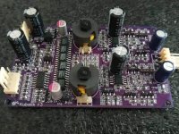
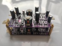
Here's the first r3 Kubelik built up which is the PCB revision for the kits. The height is 19mm which I've tried to keep as low as possible so they can be stacked. That way a balanced Kubelik is going to be under 40mm tall, with the right choice of spacers. As you can see in the 2nd image, which is made out of r2 PCBs.
Here's the first r3 Kubelik built up which is the PCB revision for the kits. The height is 19mm which I've tried to keep as low as possible so they can be stacked. That way a balanced Kubelik is going to be under 40mm tall, with the right choice of spacers. As you can see in the 2nd image, which is made out of r2 PCBs.
Attachments
The commercial kits thread is now up : https://www.diyaudio.com/forums/vendor-s-bazaar/375955-kubelik-nos-dac-kits.html#post6758243
Price in Chinese currency is 128RMB which translates at current FX rates to about USD20.
Price in Chinese currency is 128RMB which translates at current FX rates to about USD20.
Last edited:
With Kubelik launched I'm turning my attention back to ways to lower the noise in the existing DecaDAC design with a view to releasing an upgraded version. One change that produces a subjective improvement in dynamics is raising the LC filter's terminating impedance. DecaDAC uses 47ohm - right now though I'm listening to a lash-up with 330ohm terminating impedance. Going higher means the DAC chips themselves can't drive the filter directly as their compliance range isn't high enough - so a cascode MOSFET is included.
The other area to attack on the noise front is the droop correction. I've been using active filters (MFB then more recently, S-K) to do this to date but I'm curious whether modification of the LC filter might sound better. The Chebyshev template for creation of LC filters has a flat passband but I've found that by tweaking the value of first cap in the filter a peak at the filter corner frequency can be introduced. One downside of this modification is the loss of headroom at the top of the audio band. That needs to be weighed against the potential increase in transparency resulting from deleting the final S-K stage. This trade-off it seems can only be explored through listening.
The other area to attack on the noise front is the droop correction. I've been using active filters (MFB then more recently, S-K) to do this to date but I'm curious whether modification of the LC filter might sound better. The Chebyshev template for creation of LC filters has a flat passband but I've found that by tweaking the value of first cap in the filter a peak at the filter corner frequency can be introduced. One downside of this modification is the loss of headroom at the top of the audio band. That needs to be weighed against the potential increase in transparency resulting from deleting the final S-K stage. This trade-off it seems can only be explored through listening.
Attachments
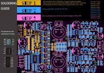
Kubelik soldering guide
Here's a graphic with TP target voltages to guide you through the build and test process for Kubelik.
You'll need a 20VDC power supply with at least 100mA capability.
In step1 (gold coloured) you put down the shunt regulators for the I2S logic and DAC chips, along with the mid-rail reference. Solder the 6 DAC chips last and only connect their power pins (4,5) at first because its possible you'll find a faulty one and it'll be easier to remove with only two pins soldered. Power up and verify the supplies for logic, DAC and mid-rail voltages. Then check pin7 voltage on each DAC chip, a faulty chip will have a large discrepancy from the target value. To complete step1, power down and solder remaining DAC chip pins.
Step2 (blue) consists of the rest of the SMD components. Only fit the 0R resistors at the outputs if you plan to use off-board coupling caps. SOT resistors aren't fitted. Fit the 2N7002 MOSFETs last as they're quite sensitive to static discharge. Power up and measure the 4 TPs on the right side which should be at mid-rail.
Step3 (pink) is the through-hole components - caps and inductors. The caps and inductors (if you have P14s) do need to be mounted the right way round. For the P14 inductors only two of the four pins are connected to the coil and those soldered pins should be innermost on the PCB. Mouser sourced inductors only have two pins and aren't directional.
Having completed step3, power up with an I2S signal playing and verify the offset voltages at TP4, TP5. If you want to gild the lily the offset can be trimmed closer to mid-rail with the SOT resistors.
Attachments
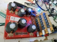
I think a better upgrade (though a bit wild to implement) would be to stack another 6 TDA1387s on top of the 6 already there and substitute lower noise opamps (maybe OPA1612?). This would also need an inductor change but should give a higher SNR.
To piggyback another 6 TDA1387 on the 6 that are on the R3 Kubelik, is there any change needed to the power supply rail parts on the board? The inductor change you are referring to is the P14? Any recommended parts for that?
Piggy-backing 6 chips will require quite extensive mods - the filter inductors and capacitors will need changing for example. I'm happy to work out all the new component values if you can get replacement inductors - they'd need to be 10mH.
It will be easier to start out just piggy-backing 3 extra chips and see if there's any change apparent. The mods then can be done without changing the inductors. For 3 extra TDA1387s you will need to increase the current feeding the DAC supply shunt regulator (U2, TL431). At present the DAC supply comes via the series combination of R11,R20 & R39 - these will need to be reduced in value so as to provide the extra current needed. But they'll then get rather too hot so probably better to change all 3 of them to a single through-hole resistor rated at 2W, 330R.
Next is to uprate the current sources which provide a bipolar current output from the unipolar DACs. The resistors which will need changing are R57,R58,R2 & R66. I need to run LTSpice to get the new values so will post these up in a while.
The other change is to reduce the I/V stage gain. This is set by R41,R61 - the new value for these is 750R.
These are the new inductors for the 12 chip mod - and Mouser even has stock : https://www.mouser.com/ProductDetail/Bourns/RL181S-103J-RC?qs=%2Fha2pyFaduhSCbvKDf36IMklej57%2FPRTbz2u5uTJYJwN%252BSaflGZKVQ%3D%3D
The only downside I can think of for doing the 3 chip piggy-back is you'll lose the headroom for intersample overs. The 6 extra chip mod won't have that disadvantage because the inductors are changing.
Next is to uprate the current sources which provide a bipolar current output from the unipolar DACs. The resistors which will need changing are R57,R58,R2 & R66. I need to run LTSpice to get the new values so will post these up in a while.
Computer says R57,R58 change to 56R ; R2,R66 change to 91R.
- Home
- Source & Line
- Digital Line Level
- lingDAC - cost effective RBCD multibit DAC design