Hi Bart - he linked to it in an earlier post here : lingDAC - cost effective RBCD multibit DAC design
Hi Bart - he linked to it in an earlier post here : lingDAC - cost effective RBCD multibit DAC design
Ahaa thanks
")
Reconstruction filter design
Seeing as the 7th order filter sounds better than the 3rd order I have been wondering whether a 7th order filter is the pinnacle subjectively or whether its worth exploring even more complex filters. The filter type which performs best in the frequency domain is called an 'Elliptic function filter' or sometimes a 'Cauer' filter.
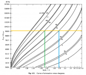
The bible of elliptic function filter design seems to me to be a very thick book by Anatol Zverev - its the one used as a reference in Arthur Williams' filter design book. Its much more mathematical than Williams' book - my math certainly isn't up to the job. Fortunately though he provides some graphs and tables where the math has been taken care of so relative math dunces like me can get useful info out. One such useful graph I've attached below - it shows how complex a filter is needed given certain parameters regarding steepness and stop-band rejection are known.
The sloping black lines represent individual filter orders and the Y axis corresponds to stop-band rejection. I've drawn a yellow horizontal line at 96dB - this is normally the target stop-band rejection for a 16bit DAC. On the X axis is the steepness of the filter expressed as 'Omega' - the ratio of the frequencies start of the stop band to the end of the passband. Steepness is decreasing as the 'Omega' ratio increases from left to right.
The vertical green line shows that for a 9th order filter we'll get an Omega ratio something around 1.25. If we allow a passband to 20kHz this means our (-96dB) stop band will start at 25kHz. If we specify that we want the stop band to begin at 24.1kHz then this tells us our passband will end at 19.3kHz. So it looks as though a 9th order filter will give us almost a textbook reconstruction filter in terms of amplitude response. The caveat is that the graph represents ideal filters with zero losses and zero tolerance components. My 7th order filter doesn't come very close to the cyan line performance on this graph because it wasn't designed as a true elliptic filter, rather it takes into account non-ideal Q inductors and also quantized inductance values.
Seeing as the 7th order filter sounds better than the 3rd order I have been wondering whether a 7th order filter is the pinnacle subjectively or whether its worth exploring even more complex filters. The filter type which performs best in the frequency domain is called an 'Elliptic function filter' or sometimes a 'Cauer' filter.
The bible of elliptic function filter design seems to me to be a very thick book by Anatol Zverev - its the one used as a reference in Arthur Williams' filter design book. Its much more mathematical than Williams' book - my math certainly isn't up to the job. Fortunately though he provides some graphs and tables where the math has been taken care of so relative math dunces like me can get useful info out. One such useful graph I've attached below - it shows how complex a filter is needed given certain parameters regarding steepness and stop-band rejection are known.
The sloping black lines represent individual filter orders and the Y axis corresponds to stop-band rejection. I've drawn a yellow horizontal line at 96dB - this is normally the target stop-band rejection for a 16bit DAC. On the X axis is the steepness of the filter expressed as 'Omega' - the ratio of the frequencies start of the stop band to the end of the passband. Steepness is decreasing as the 'Omega' ratio increases from left to right.
The vertical green line shows that for a 9th order filter we'll get an Omega ratio something around 1.25. If we allow a passband to 20kHz this means our (-96dB) stop band will start at 25kHz. If we specify that we want the stop band to begin at 24.1kHz then this tells us our passband will end at 19.3kHz. So it looks as though a 9th order filter will give us almost a textbook reconstruction filter in terms of amplitude response. The caveat is that the graph represents ideal filters with zero losses and zero tolerance components. My 7th order filter doesn't come very close to the cyan line performance on this graph because it wasn't designed as a true elliptic filter, rather it takes into account non-ideal Q inductors and also quantized inductance values.
Attachments
Zverev's copious tables don't reach up as high as 9th order elliptic filters so if I'm going to design my almost-textbook reconstruction filter I'll have to find a different route. There is an excellent online resource here for elliptic filter design - RF Tools | LC Filters Design Tool. Filter orders up to 20th are allowed, the downside is only equally terminated filters and mine isn't one of those.
What the RF tools site does permit is visualizing how close a 9th order design gets to a textbook reconstruction filter. The answer is - not as close as Zverev's graph indicates - I need to reduce the passband to 18kHz to achieve -96dB at 24.1kHz. This tool is the most useful online filter calculator I've so far seen - a really powerful facility to have, kudos to the writer.
What the RF tools site does permit is visualizing how close a 9th order design gets to a textbook reconstruction filter. The answer is - not as close as Zverev's graph indicates - I need to reduce the passband to 18kHz to achieve -96dB at 24.1kHz. This tool is the most useful online filter calculator I've so far seen - a really powerful facility to have, kudos to the writer.
Hi Richard,
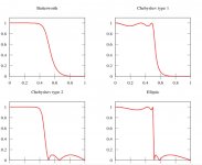
Found the nice pic below at: Linear filter - Wikipedia
IIRC, reason elliptical filters are not used more often in hifi is passband ripple and possible audibly objectionable phase response (for at least some people). But if you have one that sounds good with your dac that's all that matters.
Found the nice pic below at: Linear filter - Wikipedia
IIRC, reason elliptical filters are not used more often in hifi is passband ripple and possible audibly objectionable phase response (for at least some people). But if you have one that sounds good with your dac that's all that matters.
Attachments
Helpful pic there, thanks Mark. I've always assumed that phase distortion can be corrected in the digital domain so haven't worried about it - if it becomes audible its an excuse to include an MCU in the DAC. My 7th order filter isn't a true elliptic filter but likely has quite similar (though lower) phase distortion.
From the picture its clear that elliptic filters exhibit the sharpest transition from passband to stop band of the available types. What the textbooks don't tell you though is how to get that pretty shape in practice with real, lossy components. NP0 capacitors are extremely high Q so rarely are a problem, provided one has enough of them. Inductors though are much lower Q in practical sizes.
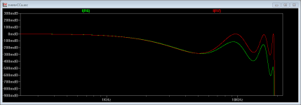
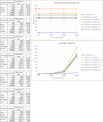
I've attached a plot that I got from running an LTSpice sim of two elliptic filters - one with almost zero losses (Qs above 10,000) and the other with P14 inductors with their typical Q around 200. The finite Q gives rise to a couple of effects on the filter's passband - uneven ripples and droop towards the transition band.
From the picture its clear that elliptic filters exhibit the sharpest transition from passband to stop band of the available types. What the textbooks don't tell you though is how to get that pretty shape in practice with real, lossy components. NP0 capacitors are extremely high Q so rarely are a problem, provided one has enough of them. Inductors though are much lower Q in practical sizes.
I've attached a plot that I got from running an LTSpice sim of two elliptic filters - one with almost zero losses (Qs above 10,000) and the other with P14 inductors with their typical Q around 200. The finite Q gives rise to a couple of effects on the filter's passband - uneven ripples and droop towards the transition band.
Attachments
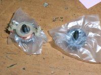
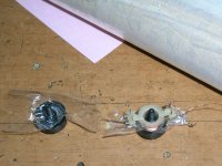
I run a test on the effect of increasing gap btn the two halves of the P14-8 ferrite on the inductance of wound coil.
For spacer I used small pieces of plastic food bags and later mylar food wrap foil both of which are half a mil thick (0.0005inch=12.7um).
I wound 70 turns of 10x0.0007m twisted enamel wire over the coil former. The plastic screw was set finger tight. I measured inductance and Q
Results show the inevitable effect of tension variation (finger sense,no torque tester) but this effect is much less abrupt than on no-gapped ferrites.
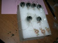
I decided to wind all the six coils (for the 7th order filter) using 2 layers of mylar food wrap.
It ended to be 69turns for the 502uH and 63 turns for the 400uH. I make the L, Q measurement for some days to see for change due compressibility of the plastic foil and/or relaxation of plastic screw tension.
I’ll report back on this.
George
For spacer I used small pieces of plastic food bags and later mylar food wrap foil both of which are half a mil thick (0.0005inch=12.7um).
I wound 70 turns of 10x0.0007m twisted enamel wire over the coil former. The plastic screw was set finger tight. I measured inductance and Q
Results show the inevitable effect of tension variation (finger sense,no torque tester) but this effect is much less abrupt than on no-gapped ferrites.
I decided to wind all the six coils (for the 7th order filter) using 2 layers of mylar food wrap.
It ended to be 69turns for the 502uH and 63 turns for the 400uH. I make the L, Q measurement for some days to see for change due compressibility of the plastic foil and/or relaxation of plastic screw tension.
I’ll report back on this.
George
Attachments
Interesting George - so you have converted your AL160 cores into AL115. What's the temperature coefficient of expansion of mylar film?
You'll have slightly lower Q coils than the original design but I doubt the extra losses will significantly alter the FR.
Where did you get your no-gap ferrites?
You'll have slightly lower Q coils than the original design but I doubt the extra losses will significantly alter the FR.
Where did you get your no-gap ferrites?
I got my no (intentional) gap ferrites here:
PhiDAC hex kits with pre-built filters
Thermal expansion coefficient is very benign but a few other surprises here:
http://usa.dupontteijinfilms.com/wp-content/uploads/2017/01/Mylar_Physical_Properties.pdf
What is AL160 and AL115?
George
PhiDAC hex kits with pre-built filters
Thermal expansion coefficient is very benign but a few other surprises here:
http://usa.dupontteijinfilms.com/wp-content/uploads/2017/01/Mylar_Physical_Properties.pdf
What is AL160 and AL115?
George
Oh, I hadn’t noticed there is a gap at the inner ring.
I just checked it and verified your words. With my mechanical caliper I can measure 0.2mm (0.008inch) height difference btn outer ring and inner ring (total, both halves). Thanks Abraxalito for this valuable info.
Now, this means that I do not have to mess with increasing the existing gap adding more uncertainty to the long term stability of coils electrical parameters.

George
I just checked it and verified your words. With my mechanical caliper I can measure 0.2mm (0.008inch) height difference btn outer ring and inner ring (total, both halves). Thanks Abraxalito for this valuable info.
Now, this means that I do not have to mess with increasing the existing gap adding more uncertainty to the long term stability of coils electrical parameters.
George
You were watching!!!The ones we sold you do have a gap, its the only way to get close enough tolerance for an inductor. Ungapped inductors would be +/-30% or so.
You mean independently decoupling each chip with a cap? I haven't done that but I've nothing against it. Yes, I use two caps for decoupling six chips - the 1uF ceramic and a 2700uF 'lytic.
Yes, I meant that. I was a bit disappointed to see that your board doesn't have independent decoupling for each chip. In technical aspect, I expect you to follow datasheet layout directives just like other Ebay,Aliexpress tda1387 boards did.
Have you any plan to alter board layout in near future?
You may aware of that each dac chip doesn't perform same since their physical distance to the "single" low impedance decoupling point isn't equal. This means parallel operation is not optimum.
If you are familiar with Nobsound TDA1387 board, you can follow same route by placing decoupling caps beneath the chips.
If you are familiar with Nobsound TDA1387 board, you can follow same route by placing decoupling caps beneath the chips.
Each designer has his/her own way.
But It is not a good sign for a designer to expose any fundamental circuit layout design mistakes. Designers choose different ways to do things better, not the worse.
If you continue to defend your decisions this way, how it is going to be possible to allow any contributions from any other DIY'er unless you don't call this "one man show".
But It is not a good sign for a designer to expose any fundamental circuit layout design mistakes. Designers choose different ways to do things better, not the worse.
So far its only your opinion that its worse. If you show some results of experiments - for example do some listening both with and without caps, or make some measurements then we'll have something to talk about.
If you continue to defend your decisions this way, how it is going to be possible to allow any contributions from any other DIY'er unless you don't call this "one man show".
I haven't got anything to defend here. If you don't like my design choice in respect of decoupling then there are plenty of DACs which follow your notion of correctness on Taobao. I also can't see how this particular choice is related to what other DIYers might say - do please elucidate.
You've made it clear you are 'disappointed' - that's an entirely subjective position to hold. I see no reason to make design changes in response to someone's disappointment. Do some experiments yourself then you're bringing something tangible to the table.
So far its only your opinion that its worse. If you show some results of experiments - for example do some listening both with and without caps, or make some measurements then we'll have something to talk about.
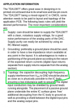
You were right if I was about some personal preference like different value, brand of any component but we are talking about some fundamental design considerations here. What about taking a look at corresponding DS section below?
I haven't got anything to defend here. If you don't like my design choice in respect of decoupling then there are plenty of DACs which follow your notion of correctness on Taobao. I also can't see how this particular choice is related to what other DIYers might say - do please elucidate.
Even if your "design choice in respect of decoupling" in contradiction with Philips engineers whom also stating voltage compliance values on same datasheet? Yes you are free of choosing different value of voltage compliance too but I'm also free to bring "your own design of choice" on table without building, testing and measuring since DS says something different.
You've made it clear you are 'disappointed' - that's an entirely subjective position to hold. I see no reason to make design changes in response to someone's disappointment. Do some experiments yourself then you're bringing something tangible to the table.
Subjective? I thought you were aware of that I was suggesting you to just respecting the DS. Because I'm bringing on table something much less "subjective" than PCB color of choice.
Attachments
Last edited:
it introduces the chance of meta-stability in the reclocking FFs, something that's best avoided.
It is metastabile only in the way when 1 x flip flop is used per digital line.
And that wrong way is most common.
But when designed as in school literature, with 2 cascaded, serial flip-flops, it is not metastabile. And all lines should be "reckloked".
Second thing is that clocking signal should be minimum 2x times higher Fr.
That is the master clock. When BCK is equal to the master clock recklocking simple can not work...
- Home
- Source & Line
- Digital Line Level
- lingDAC - cost effective RBCD multibit DAC design