... I have learned with electronics is that it is part science and part magic. ...
... for you. No magic, just lack of knowledge
//
... for you. No magic, just lack of knowledge
//
Wow looks like we've got a Guru here
@TNT My neighbor is an electrical engineer at a nuclear power station near me and we have fun talking about circuits. He thinks like you do. If a circuit requires 10uf then 10uf is what makes it work. And I agree. If I need to replace a capacitor in my garage door opener then I replace it with whatever voltage and capacitance it requires. BUT, and as you can see it is a big but, audio is a weird animal where the technical measurements and the human measurements do not always align. How do you measure perceived width of a sound stage? How do you measure instrument location? There is a huge difference between a Panasonic FC and an Elna Silmic. It is not esr and esl and capacitance. There is a certain je ne sais quoi that you have to play with. The materials themselves have a sound. I know the sound of silver mica, the same way I know how Niobium sounds or Panasonic FC.
This is why you look at one woman and you respond positively, while towards another you don't. They both measure as "women" and can perform the essential functions of "women" and looking at government statistics they might be indistinguishable and interchangable, but there is a difference....
This is why you look at one woman and you respond positively, while towards another you don't. They both measure as "women" and can perform the essential functions of "women" and looking at government statistics they might be indistinguishable and interchangable, but there is a difference....
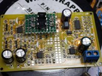
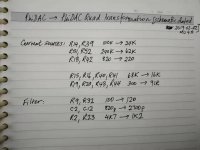
Its Chinese New Year's Day here so I decided to get into the holiday swing by forgetting about GrossDAC and having a play with PhiDAC again, inspired by @sajunky's questions back in the autumn regarding adding more DAC chips. Turns out I was a little bit pessimistic about how hard it is - increasing the chips to 4 (rather than 8 as mentioned by @sajunky) isn't too hard at all. Only one capacitor (per channel) needs to be changed - that's C2/C12. 4 chips doesn't exceed the current rating of the MLF inductors so they stay as they are, various resistor values do need tweaking.
Initial listening seems to show that the low frequency ambience gets better with more chips. So this lends support to the idea that paralleling could be why GrossDAC has the best ambience retrieval of any DAC I've played with. But its early days yet, don't read too much into this very preliminary conclusion.
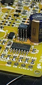
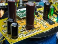
In my test-bed DAC I've placed the filter components on a daughter board for ease of fiddling with them. DAC chips are stacked in the traditional way by bending the leads of the upper chips inwards then bridging between them with solder. Its very easy to miss an open circuit with this method, be sure to check continuity with a multimeter.
Attachments
Now I understand why a price for PhiDAC has doubled. I thought it were rather better caps in a kit, but now I will ask for more DAC chips. 
A practical tip: When stacking chips vertically I put a thin quality wire along from the top to the bottom, especially for Vcc, GND. Otherwise these series of joints may not work properly.
A practical tip: When stacking chips vertically I put a thin quality wire along from the top to the bottom, especially for Vcc, GND. Otherwise these series of joints may not work properly.
OK - you didn't convince me. But its ok.
//
//
@TNT My neighbor is an electrical engineer at a nuclear power station near me and we have fun talking about circuits. He thinks like you do. If a circuit requires 10uf then 10uf is what makes it work. And I agree. If I need to replace a capacitor in my garage door opener then I replace it with whatever voltage and capacitance it requires. BUT, and as you can see it is a big but, audio is a weird animal where the technical measurements and the human measurements do not always align. How do you measure perceived width of a sound stage? How do you measure instrument location? There is a huge difference between a Panasonic FC and an Elna Silmic. It is not esr and esl and capacitance. There is a certain je ne sais quoi that you have to play with. The materials themselves have a sound. I know the sound of silver mica, the same way I know how Niobium sounds or Panasonic FC.
This is why you look at one woman and you respond positively, while towards another you don't. They both measure as "women" and can perform the essential functions of "women" and looking at government statistics they might be indistinguishable and interchangable, but there is a difference....
Now I understand why a price for PhiDAC has doubled. I thought it were rather better caps in a kit, but now I will ask for more DAC chips.
BOM cost for PhiDAC still the same at $3 (assuming parts bought from Taobao, not Mouser). Perhaps you're referring to prices of kits? - they'll always be more expensive due to the labour element (ordering, labelling, bagging etc.). The fewer DACs per kit the higher the relative labour costs - which is why I originally only advertised kits of 10. If you ask for special builds (additional DACs) the labour content will explode
Has anyone any suggestions for the name of the new DAC for 2020 (or Year of the Rat) - I was thinking PhiDAC Quad? The BOM cost isn't going to be much more than for PhiDAC, maybe $4. I am thinking keep the AD8017s from the original PhiDAC (smaller PCB area) but use the AD815 as supply regulator (as on PhiDAC SE). This will mean a wider supply voltage range - say 10-15V.
A practical tip: When stacking chips vertically I put a thin quality wire along from the top to the bottom, especially for Vcc, GND. Otherwise these series of joints may not work properly.
Have done that on various builds - becomes virtually mandatory when stacks of more than 4 chips are built. But I figured with 4 I would go for just solder.
Unfortunately I can't sell 10 kits here in South Africa.BOM cost for PhiDAC still the same at $3 (assuming parts bought from Taobao, not Mouser). Perhaps you're referring to prices of kits? - they'll always be more expensive due to the labour element (ordering, labelling, bagging etc.). The fewer DACs per kit the higher the relative labour costs - which is why I originally only advertised kits of 10. If you ask for special builds (additional DACs) the labour content will explode
Has anyone any suggestions for the name of the new DAC for 2020 (or Year of the Rat) - I was thinking PhiDAC Quad? The BOM cost isn't going to be much more than for PhiDAC, maybe $4. I am thinking keep the AD8017s from the original PhiDAC (smaller PCB area) but use the AD815 as supply regulator (as on PhiDAC SE). This will mean a wider supply voltage range - say 10-15V.
The name is important. As long I can make my first board from a kit, I would say: 恭喜发财 PhiQuad.
Henry Ford used to say: "If everyone is moving forward together, then success takes care of itself".
Amoung of using more DAC chips and aligning to a common PSU voltages, I like the idea of a having filter on a separate board, so I can swap modules when testing different sample rates or preferences.
Chineese rat is a zodiac sign, a different one from a Babylonian astrology that leaked through the Hellenistic culture to us.
Astrological sign - Wikipedia
Not sure whether giving such name to a DAC is appropriate. Not a living person as such that can be influenced by stars, and to influence other people. But maybe Chineese can do?
Astrological sign - Wikipedia
Not sure whether giving such name to a DAC is appropriate. Not a living person as such that can be influenced by stars, and to influence other people. But maybe Chineese can do?
On your first question, I don't know. I haven't tried with just 2 chips, I figured why not stack up 4 for a first attempt as that'll give 6dB reduction in DAC noise and also improve the SNR of the following stages (by increasing the S without changes to the N). 4 chips is about the limit for the first filter which is made up of tiny (0805) inductors with a maximum current rating of 5mA (each DAC chip, running on 6V contributes 1.2mA).
The filter that needs to change for 4 chips isn't the first stage (CLC) one, its the second stage (active) one. That changes because its not just a filter, its also a gain stage and we need lowered gain when the DACs put out more current. If we didn't lower the gain the output would clip at -12dBfs because we have 4X as much current. When the gain changes, the last stage capacitor also needs to change as its bootstrapped around the opamp - with less gain the cap gets less bootstrapping and hence its effective capacitance goes down. So we just increase its value (820pF to 2n7) to compensate.
The filter that needs to change for 4 chips isn't the first stage (CLC) one, its the second stage (active) one. That changes because its not just a filter, its also a gain stage and we need lowered gain when the DACs put out more current. If we didn't lower the gain the output would clip at -12dBfs because we have 4X as much current. When the gain changes, the last stage capacitor also needs to change as its bootstrapped around the opamp - with less gain the cap gets less bootstrapping and hence its effective capacitance goes down. So we just increase its value (820pF to 2n7) to compensate.
Last edited:
On your first question, I don't know. I haven't tried with just 2 chips, I figured why not stack up 4 for a first attempt as that'll give 6dB reduction in DAC noise and also improve the SNR of the following stages (by increasing the S without changes to the N). 4 chips is about the limit for the first filter which is made up of tiny (0805) inductors with a maximum current rating of 5mA (each DAC chip, running on 6V contributes 1.2mA).
The filter that needs to change for 4 chips isn't the first stage (CLC) one, its the second stage (active) one. That changes because its not just a filter, its also a gain stage and we need lowered gain when the DACs put out more current. If we didn't lower the gain the output would clip at -12dBfs because we have 4X as much current. When the gain changes, the last stage capacitor also needs to change as its bootstrapped around the opamp - with less gain the cap gets less bootstrapping and hence its effective capacitance goes down. So we just increase its value (820pF to 2n7) to compensate.
That is quite a jump from 820pf to 200uf! I suppose I will just solder the 200uf on top of the existing cap. Does not seem to make much sense removing it. Does anyone know a reputable ebay seller for TDA1387?
- Home
- Source & Line
- Digital Line Level
- lingDAC - cost effective RBCD multibit DAC design


