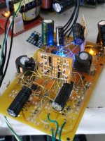
Latest prototype with OPA1678
This is the latest incarnation of the 'reloaded' PhiDAC - I've been listening to it for a couple of hours so far and its strength is definitely in the region of HF transparency. The obvious weakness though is in bass solidity in comparison to a tweaked Deca DAC (which uses LT1028). This combination of strengths/weakness give the overall impression that its a bit on the bright side in tonal balance.
My hypothesis is that its the LF noise in the opamp that's responsible for this tonal balance so I plan to try other opamps with lower LF noise corners. The OPA1678 being CMOS input is considerably worse for LF noise than a typical low-noise JFET opamp. OPA1642 is the next candidate to try - however its at least 3X the cost.
Anyone got any other ideas for low noise opamps to try out, preferably duals?
Attachments
Funny you should mention that one Vunce, it was the first DS I pulled up when looking around. Turns out the LF noise issue is the same as for OPA1678 - HF-wise its slightly better but LF noise density @20Hz is the same 25nV. So if my hypothesis is correct it might sound a teensy bit brighter than OPA1678.
I still have a bag of AD829 so I'm going to try again with that for the next proto. Its bipolar though so might need some R values tweaked.
I still have a bag of AD829 so I'm going to try again with that for the next proto. Its bipolar though so might need some R values tweaked.
")
My affair with CFBs is pretty much over now because in practice they are a bit noisy - I'm interested in VFBs once again and OPA1678 seems to deliver a very good package of features at a very nice price.
I can say pretty much the same about AD811. I try it (Jung transimpedance arrangement). Sound is very good BUT it was very hot even with not so small heatsink. I had to lower PS value and increase heat sink to minimise temperature to some acceptable level for long time opperation. Heatsink was bigger than Jung proposed and PS was if i am remember well +-12V?
Decoupling should be good and other things for preventing IC to oscillate.
I think that one heatsink should be added on the bottom on that chip somehow, but it deserves different mounting design of the IC? Sort of sandwich IC between 2 heatsinks maybe.
My hypothesis is that its the LF noise in the opamp that's responsible for this tonal balance so I plan to try other opamps with lower LF noise corners.
Seems I have been a little bit too hasty to lay the noise floor imbalance at the feet of the opamps. The design had been working on a single TDA1387 - I wondered if adding more chips might add more bass? And indeed, going from one to two chips does flesh out the sound so it sounds a good deal more in balance. So here is an audible justification for running more than one chip in parallel - LF noise is decreased which gives more perceived depth and a more 3D presentation. Perhaps OPA1678 can stay after all, more listening needed.
Sorry for off topic but I'm using supercaps to power a single TDA1387 and recently added a 1 ohm resistor between the regulator and load as a test, the idea being to isolate the reg output from the low ESR caps and supercaps and also provide some more filtration.
I have not evaluated what it does to the sound because of an issue, the supercaps slowly discharged over the course of hours with the 1 ohm resistor in series and they wont charge unless it is shorted.
If the supercaps are removed there is only a very small voltage drop across the resistor, as you'd expect with tda1387 low current consumption, so I figure it must be leakage current from super caps.
According to datasheet it should be pretty insignificant so that doesnt explain it, unless the caps are damaged.
I need to ask, am I overlooking something obvious here? because it certainly feels like it.
I dont recall any happening that could have damaged them, I probably never would have known of this possible issue without this test... so in a way it was a good thing
Forgot to add, it is 4 3V supercaps (2 series pairs in parallel for 6V with the same capacitance), I split them up and both pairs have the problem, it seems even more unsual they could all be faulty like this without a clear cause which is why I feel strongly like Im missing something.
The quoted leakage current did seem oddly low (150uA for 50F), most solid polymer lytics have higher leakage than this...
Last edited:
It turns out super caps need to be charged for a given time for leakage current to stabilise to the datasheet value, I thought 72 hours in datasheet was just for first time break-in, kind of cool that this reflected my experience of them going through an audible 'warm up' phase for few hours after they reach full voltage.
I dont really understand what counts as 'charging',
What if it is being heavily discharged throughout the 72 hours aswell (not that they would be in this case)?
It was after 24 hours that I noticed lower volume from the TDA1387 and discovered the voltage drop... You would expect after 24 hours leakage would have become low enough for voltage to start climbing again, or not since it was stuck in a state of slow discharge.
Thinking about it more, the only reason the supercaps were able to be discharged was because they were still fully charged from before and they had been connected to the supply for a while, so the leakage is still unusual...
Last edited:
I understand OPA1656 might not give a huge improvement on the paper over your current OPA choice, but sometimes spec sheet aren't the entire thing.
I would say give it a try amazing OPA on many applications. Having said that, it is quite neutral, not bass heavy, so depending on how you want to trim the balance you may not prefer it. It is quite musical / natural, but then perhaps you rely on the output transistors for sonic performance.
As said, if you have them lying around, would be pity not to try the OPA1656, they are non expensive...
Just thinking out loud of course, and following all your developments with delight, thanks for sharing all this
Claude
@lasercut - I've a little experience with supercaps for powering DACs. What circuit are you using to charge them? To get them up to working voltage from 'cold' takes either a lot of current or alternatively a long time. For example with 1A into 50F the voltage rises 1V every 50s so you need 250s to reach 5V. If your 1ohm resistor is a small one (SMD 1206 for example) then it may have overheated and gone either open or much higher resistance. The leakage current seems reasonable, its lower than with polymers.
@ClaudeG - thanks for your suggestion. I agree spec sheets aren't everything when it comes to how things sound. Yes I do rely on the output transistors for getting the SQ I like, I did try without them and didn't find the sound engaging on more complex music. Seeing as the main difference I noticed between 1656 and 1678 was in output drive I felt like I wasn't paying for what I didn't use in selecting the 1678.
@ClaudeG - thanks for your suggestion. I agree spec sheets aren't everything when it comes to how things sound. Yes I do rely on the output transistors for getting the SQ I like, I did try without them and didn't find the sound engaging on more complex music. Seeing as the main difference I noticed between 1656 and 1678 was in output drive I felt like I wasn't paying for what I didn't use in selecting the 1678.
So... perhaps you could try OPA1656 and even try that one without the output transistors.
If you get the sonic signature you want with the drive capability, you would this way even get a circuit with less parts and cost... and who knows, might even sound better.
On another note, my very own DAC is similary built (with different DAC chip) and runs at 10V instead of 2V RMS at the output... and indeed it seems that running higher voltage has some benefits, albeit not necessarely that high.
Good luck and have fun experimenting
Claude
I also plan to run at higher output levels - more signal, same noise. But then I need to adopt different step-down transformers in my amps to deal with that.
In my multiple parallel DACs thread I have prototyped a DAC with 36V output swing (balanced 18V peak-to-peak) and agree on the benefits of that. Incidentally this new PhiDAC will run at higher supply to allow it to cope with intersample overs. I plan to test that capability in the next few days.
When you say your DAC is similarly built, whose inductors are you using in your filter? Or don't the similarities go that far?
Nope, they don't go that far.
My build is over 20y old, I was one of the guys who developped the ART I/O tweaks back then with little knowledge compared to today.
AKM chip (then not that known), a CODEC in fact, followed by AOPs biased in class A with transistors. The AOPs are AD825 and the transistors are back then easily available 2SK170 LOL. Hope no one ,ow intend to rip off my old DAC.
I recently had to chose a DAC for a friend and we did many shootouts (he had them for over a month on a loan) and at the end of the day the winner (D70S) isn't sounding any better than my DAC, but they are very close (wheread there were massive differences with all other DACs). Of course my DAC then only does DAC, not even volume correction and has only a cinch digital input, so features can't be compared (bluetooth etc.)
Bottom line for me: DAC chip and maxi spec figures aren't the key, wasn't the case 20y ago then when I tried many many commercial DACs regardless the price, and isn't today. SINAD & Co are meaningless and yes sonic differences are massive between DACs, or rather say between the DACs the mere mortals can afford, but I am not sure most of these have ever experienced high end DACs (re sound, not necessarly price) or are educated re listening (mu mother and grand mother are / were world class opera singers). Further, once you reach a certain point regarding satisfying sonic quality, then indeed differences (as with every component) are getting thin and it is difficult to justify higher price tags other then with sonic signature preferences (say different sound flavours). You can have today good sounding commercial DACs for less than 1000$.
I am following this thread with great interest because I like your developments and in a near future I will need another DAC for my secondary system in coming, something I wish affordable but very balanced re sound. And why not some DIY while at it, and / or learning while at it some programming & Co. That system will go in the leaving room and will be articulated around the VFET amp I am fortunate to build and presumably a pair of Klipsch RP-8000F. For this secondary system I am not seeking absolute sound quality, but a nice one as we will be listening to it probably more then my main system (for which I am very demanding). However, it will be more modern, with younger people being able to listen via Spotify (Rasberry Pi presumably, have to dig into all that) and probably no other source. And all that will act as a preamp with volume control, so needs a reasonable digital volume control from 0dB to say -30dB.
Would be nice if one of your DAC developments could fill that bill one day, would love it to as I would rather support this than purchasing a D70S or equivalent, not even mentioning buudget
You know it all, sorry for the long post
Claude
Last edited:
An UltraBib is charging/regulating, resistor is 1W.
The part that doesnt make sense is that they were already charged up to the supply voltage from before the resistor was added and were powering the circuit for at least a day IIRC.
Replacing 1ohm with 0.33ohm was enough to overcome leakage and allow charging, after a couple days of powering I will try 1 ohm again and see if voltage still falls.
@ClaudeG - not at all too long, you have raised some interesting points.
I take it D70S is a Topping DAC using AK4497 - I have played with that chip for a short time and it definitely showed promise. Not enough to distract me from TDA1387 though. A volume control for my DAC is indeed an interesting project that I've given some thought to but not made much progress on. I shall continue to nurture it on the back burner.
Back to current DAC development, I've been playing with active and passive filters to see which type can be best optimized for noise. I've long lived with the notion that the ultimate for low noise has to be a passive (LC) type as there's only the resistance to consider there, no active element. And that resistance can be made arbitrarily low with enough space available for the wound components.
It turns out from simulating that that's only half the story with LCs - the practical realisation of them always needs some damping to be provided and its necessarily a resistor. When I simmed a 2nd order LC lowpass in LTSpice I found that the damping (which acts mostly at the filter corner frequency) is responsible for significant HF noise. So to get a very low noise LC filter requires a very low value of damping resistor and that makes the filter difficult to drive (needing lots of current).
Turning to S-K (active) filters assuming a noiseless buffer the primary noise contribution is the two Rs - to get low noise needs very low values and again, the filter becomes a current hog calling for a beefy buffer prior.
I wondered then if inductors could be used in place of resistors to make the S-K LPF easier to drive - and at least in simulation they can and do give the advantages I was looking for - lower noise whilst also being easier to drive. So I just have to build one and listen - after all the inductors might pick up noise and defeat the whole object of the exercise!
Many thanks for your kind and detailled reply.
Fascinating! I shall follow all your future developments with enthousiasm.
Yep, the D70S I mentioned is a Topping with in fact TWO AK4497 chips. perhaps overkill, but the end result is in fact quite satisfying. Enough say not to be a real bottleneck in any system with speakers below the say the 5k $range.
Having a good digital volume control in a DAC is a nice plus, although I don't know if Spotify & Co have an acceptable digital volume control (didn't try them so far, I should perhaps). Good digital volume controls allow nowadays really absolute perfectly inaudible volume control impact up to say at least -35dB. So if you get your gain chain right that opens the door to using a simple 3$ switch to control volume without any loss. Kind of low and long gear and that covers perfect 70dB adjustement range.
Good luck with all your developments and thanks for sharing this
Claude
- Home
- Source & Line
- Digital Line Level
- lingDAC - cost effective RBCD multibit DAC design