Yes, that's the one. And yes I am aware its not only applicable to ferrites. And no, I'm not losing sleep over the story, but it is interesting nevertheless.
I've got a full set of 6 air cores in my dangling inductor filter now, having a listen as I write. It is certainly no worse than the ferrite one in that I'm not hearing interference/hum/noise from having so much copper 'exposed to the ether' so to speak. Whether there's any improvement will only be determined from further back and forth listening. Its certainly a very engaging listen but then the 'stock' filter didn't seem to lack engagement factor.
I've got a full set of 6 air cores in my dangling inductor filter now, having a listen as I write. It is certainly no worse than the ferrite one in that I'm not hearing interference/hum/noise from having so much copper 'exposed to the ether' so to speak. Whether there's any improvement will only be determined from further back and forth listening. Its certainly a very engaging listen but then the 'stock' filter didn't seem to lack engagement factor.
A guide to building your PhiDAC hex kit - part1
There are a few PhiDAC hex kits now winging their way to intrepid builders - so its about time to reveal my suggested guidelines for building.
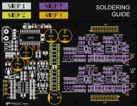
If you're like me and adopt a hand soldering approach to SMD then here's a graphic depicting which component values go where. It also outline the four stages I recommend in putting down your components on the PCB. If you prefer the hotplate or reflow method, then you can still protect the DAC chips against a PSU error - see my later post.
Stage 1 is power supply and logic
Stage 2 is DAC chips
Stage 3 is analog - I/V and filtering
Stage 4 is large capacitors then filter module.
Adopting this approach means that if you make an error on the power supply, that error hopefully won't take out other parts of the circuit - particularly DAC chips. In a subsequent post I'll tabulate the test point voltages you'll see if everything's OK at each stage.
There are a few PhiDAC hex kits now winging their way to intrepid builders - so its about time to reveal my suggested guidelines for building.
If you're like me and adopt a hand soldering approach to SMD then here's a graphic depicting which component values go where. It also outline the four stages I recommend in putting down your components on the PCB. If you prefer the hotplate or reflow method, then you can still protect the DAC chips against a PSU error - see my later post.
Stage 1 is power supply and logic
Stage 2 is DAC chips
Stage 3 is analog - I/V and filtering
Stage 4 is large capacitors then filter module.
Adopting this approach means that if you make an error on the power supply, that error hopefully won't take out other parts of the circuit - particularly DAC chips. In a subsequent post I'll tabulate the test point voltages you'll see if everything's OK at each stage.
Attachments
A guide to building your PhiDAC hex kit - part2
Test equipment - a current limited power supply, a DMM.
Assemble your PCB to 'Step1' as shown in the graphic. This populates the power supply and digital logic and level shifters. If you're using a hotplate then this step by step approach won't apply as all the components get soldered at once that way.
Apply 12V from a supply limited to ~150mA short circuit current to the power input pins at top left. If all is fine the three red LEDs will illuminate and you can check TP1 (5.5V), TP2 (8.3V) , TP3 (10V), TP4 (4.6V) and TP5 (2.5V). These voltages are all measured relative to the 0V power input terminal. Also measure across R56,R65 & R70 (these are level shifting resistors) - the reading across each should be ~4.6V.
Assuming all those are correct within ~0.1V you can progress to 'step 2'.
If the LEDs don't light then you may have mis-soldered one - then none of the TP1-3 voltages will show up correctly. Or alternatively there may be an error in the current source made up of Q4,Q8 and surrounding resistors. This CCS biasses the LEDs to create the 5.5V reference which is used as mid-rail for the analog section.
At 'step 2' solder the DAC chips (after powering down, of course!). To be extra-cautious you can replace L9 (a ferrite bead, FB) with a 1R resistor. This will allow you to check the DAC supply current - as they're recycled parts there's the very slim chance you may get one which draws too much current. On powering up again double check the voltage across the three level shift resistors again (4.6V) and also across C57. The latter should be ~3.6V. The supply current should be about 22mA, corresponding to 22mV measured across the 1R test resistor.
Assuming all is OK then proceed to soldering down all the analog parts in 'step 3'. With no filter fitted the output test points TP8, TP9 should be about 2.4V - without the filter, no DAC current reaches the I/V stage so the outputs settle to their lowest excursion.
Lastly, fit the filter connectors P3,P4, the five electrolytics and the filter module, taking care not to flex the filter PCB. Wiggle it gently from left to right to seat it in the connectors. Without an active I2S signal the TP8.TP9 nodes (easier to check from the back) will be at random voltages as up to this point, the DAC is DC coupled. With I2S active, those nodes should be 5.5V, the same as TP1.
Some progress to report with air cores
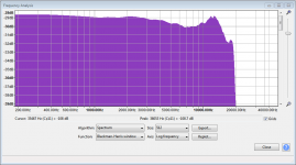
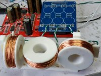
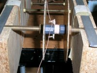
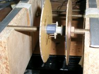
Courtesy of sterling 3D design and printing by @bdbell (big thanks there), I've now been able to assemble 3 Brooks coils onto a frame and have checked the FR. Its still rather too lumpy which means I need to investigate how to reduce the inter-coil coupling. Probably its because the coil alignments aren't giving enough cancellation, so my signal generator and AC voltmeter will need to be dusted off and employed to track this down.
Courtesy of sterling 3D design and printing by @bdbell (big thanks there), I've now been able to assemble 3 Brooks coils onto a frame and have checked the FR. Its still rather too lumpy which means I need to investigate how to reduce the inter-coil coupling. Probably its because the coil alignments aren't giving enough cancellation, so my signal generator and AC voltmeter will need to be dusted off and employed to track this down.
Attachments
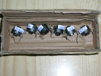
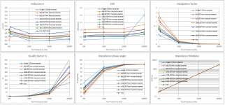
I wound six coils (in the P14 ferrites) with different wires and tested them at four frequencies (100Hz, 120Hz, 1kHz, 10kHz, 100kHz) with the DE-5000 LCR meter.
George
George
Attachments

Very interesting to see all your data George. I'm wondering what the stimulus level was? Reason being you're getting both increased inductance and increased dissipation at the lowest test frequencies - to me this is indicative of nearing saturation of the core. Qs look very impressive for the 'rope' wound coils 
Well, the (sinusoid) stimulus level is known, see last attachment above. At low frequencies where coil Z is low, stimulus level is low, less than 0.1Vrms. At higher frequencies where coil Z increases, stimulus level increases to up to 0.6Vrms.
I think I have to do some more impedance tests and wind some more coils but I don’t have any more formers/ferrites. I have to unwind some of the coils.
I should have ordered a dozen more ferrite cores and plastic bobbins.
George
I think I have to do some more impedance tests and wind some more coils but I don’t have any more formers/ferrites. I have to unwind some of the coils.
I should have ordered a dozen more ferrite cores and plastic bobbins.
George
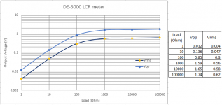
I did take a look at that plot but wasn't sure what frequency it applied at. Also the Vpp and Vrms columns don't align at the bottom - 50mVp-p isn't ~5mVRMS its ~18mVRMS.
As for more cores/bobbins, I have plenty - PayPal is your friend I have tried a filter using P18 cores rather than P14, the inductors were higher Q (made with rope) but I didn't notice any improvement in how the DAC sounded.
As for more cores/bobbins, I have plenty - PayPal is your friend
I have tried a filter using P18 cores rather than P14, the inductors were higher Q (made with rope) but I didn't notice any improvement in how the DAC sounded.It is because you still didn't experience with airgaps.I have tried a filter using P18 cores rather than P14, the inductors were higher Q (made with rope) but I didn't notice any improvement in how the DAC sounded.
As I pointed out before, controlled airgaps are required for a good sounding coil. For a reminder, it was when you was still sticking with the multiple sound polluting individually shielded SMD coils.
If you take P18 and wind it to get a twice of inductance than needed, you will have a lot of room for experiments with increasing a gap. Loss of inductance is not linear, it will decrease according to the square root formula, so there is a big advantage of using airgap. Finding an optimum airgap will be an entertaining experience, I promise.
Last edited:
I made two more coils one with 14x0.007mm twisted enamel and one with 16x0.007mm. I measured those too (1st attachment).
16x0.007 is the thicker twisted wire that can fit into the P14 core for the 502uH.
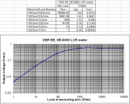
Right, thanks. I made the measurement again (2nd attachment). Instrument’s Rout is 110-150 Ohm, that’s why output varies inversely with the load.
On each load, output signal amplitude is the same at all frequencies
True. Only adjusting the tension of the attaching screw on the P14 core alters the inductance by 5% to 10%
George
16x0.007 is the thicker twisted wire that can fit into the P14 core for the 502uH.
I did take a look at that plot but wasn't sure what frequency it applied at. Also the Vpp and Vrms columns don't align at the bottom - 50mVp-p isn't ~5mVRMS its ~18mVRMS.
Right, thanks. I made the measurement again (2nd attachment). Instrument’s Rout is 110-150 Ohm, that’s why output varies inversely with the load.
On each load, output signal amplitude is the same at all frequencies
Finding an optimum airgap will be an entertaining experience, I promise.
True. Only adjusting the tension of the attaching screw on the P14 core alters the inductance by 5% to 10%
George
Attachments
Only adjusting the tension of the attaching screw on the P14 core alters the inductance by 5% to 10%
I don't get such a large change in inductance from adjusting the tension of the bolt through the middle. Perhaps its because I'm cautious - I've lost more than one core half through over-tightening, they're pretty brittle. What I do find affects the inductance rather a lot is side-to-side alignment of the cores. Tightening the nut can have the affect of shifting the top half-core laterally relative to the bottom one and this gives a significant effect.
Right Abraxalito, both axial tension and radial displacement affect inductance. Maybe the nylon screw should be a bit thicker to lessen the radial misalignment.
Surface finish after firing process can be 10 microns. For a normally flat-ground surface it is 0.5 to 1.0 microns and for a lapped core it is 0.1 to 0.2 microns.
These are not lapped cores, that’s why axial tension has a strong effect on lessening the air gap thus affecting measured inductance.
I have delicate fingers when tighting the nut.
I’ve lost a half core by dropping from 50cm to the bench surface. After that I work on them over a thick cotton bath towel.
Now fine tuning inductance maybe a wrong move. Ferrite core permeability change due to temperature variation of 20 d Celcius can be 20%. Tiny gap variation with time will have more effect.
https://www.tdk-electronics.tdk.com...2ba503/ferrites-and-accessories-db-130501.pdf
George
The ferrite material's mu does change quite markedly with temperature, that's true. However with a gapped core the inductance is determined by the gap primarily, the ferrite's permeability is a secondary factor. The Ferroxcube databook that I have shows no variation in gap size for AL160 cores made from different materials even though their mu varies 20% or so. Gap size drift would be a more important factor - the supplier of these cores told us they were made quite some years ago as these days such cores are way out of fashion. So the aging has all taken place, according to him.
<edit> A couple of pics I took in our friendly ferrite guy's roof-top store room. How old do you think these boxes are?
<edit> A couple of pics I took in our friendly ferrite guy's roof-top store room. How old do you think these boxes are?
Attachments


Last edited:
Ha ha!. Well I was not thinking about ferrite aging effect. I focused on the tiny gap variation due to nylon screw tension relaxation with time. I was thinking of stabilizing it by potting the coil/core assy after final adjustment. But then I don’t know if potting itself will change the inductance.
In the end, does air-cored inductor route provide long term merrits?
George
In the end, does air-cored inductor route provide long term merrits?
George
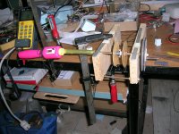
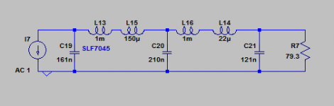
Jury's out on the air cores - I scratched my head for some time as to why I didn't get the nice smoothly undulating FR I get with ferrites. Still have not come up with an explanation, but its not inter-coil coupling as I spaced the coils well apart physically and got almost the same response. So I'll put that aside now and get back to ferrites as they're so much more practical
To celebrate my return to the ferrite fold, here's an intermediate filter idea using TDK off-the-shelf inductors. Its designed to do better than the 7th order filter in terms of stop-band suppression (>70dB above 68kHz), but only when the DAC's run 2X OS. Thus it depends on external up-sampling.
Attachments
This is called unintentional air gap.True. Only adjusting the tension of the attaching screw on the P14 core alters the inductance by 5% to 10%
George
Initially there is a very sharp change, but once airgap is larger, curve flattens.
Once you create air gap, most of energy is placed there. In result the B/H curve is linearized, so permeability, tolerances, temperature variations become also insignificant.Now fine tuning inductance maybe a wrong move. Ferrite core permeability change due to temperature variation of 20 d Celcius can be 20%. Tiny gap variation with time will have more effect.
https://www.tdk-electronics.tdk.com...2ba503/ferrites-and-accessories-db-130501.pdf
George
Air coils are ideal from THD point of view (it would be a perfect marketing catch too), but in a DAC application, it would require shielding and who knows what effect it would bring. Gapped ferrites bring what we can call - a practical solution. A mix of the best: low THD and relatively good shielding.
It is why I was talking about gapped coils when criticising dozen of tiny individually shielded SMD coils.
I understand your doubt about neccessity of fine tuning inductances. I also thought the same, but didn't want to discourage experiments. It is a fact that there is no commercial NOS DACs with a high order LC filters. We are now going to understand a reason. It is a real challenge. In this design (a filter before I/V conversion), it is even worse, as it require a filter to behave properly up to 30MHz. It is a requirement difficult to achieve.
In other words, this initial reaction to the air coils idea made a point: lingDAC - cost effective RBCD multibit DAC designTo celebrate my return to the ferrite fold,...
Stiil no talks about airgapped ferrites... Take a time.
It is a real challenge.
I get no satisfaction using a ready made product (call me a masochist)
Gapped ferrites bring what we can call - a practical solution.
When ferrite cores arrive, I will try the intentional air gap
George
PS. The aspirin trick works, thanks (an outdoors activity)
- Home
- Source & Line
- Digital Line Level
- lingDAC - cost effective RBCD multibit DAC design