Going back over some old blog posts I see that 2012 was the previous high point for DAC chip usage - here I used 40 chips : DACalito - transversal modification of DAC-AH Lite - diyAudio
So perhaps we need to multiply the sinewave by a slowly increasing function? If its sinusoidal with a constant frequency then the next maximum will occur in 2026
I've been reflecting on the engineering need for more chips and realized that using so many does solve at least one of the issues which has been bugging me with PhiDAC. That is the variation of the gain - an individual chip has something like a 14% tolerance on its output current. An array of 64 will reduce this by around 8 times assuming a normal distribution (which is perhaps a doubtful assumption). The transformer solves another issue - DC offset - as well as reducing the summed output current to a manageable level.
First prototype 64-chip DAC
I've wired the DAC chips on their ends - fortunately that's where both power pins are located. Then run wires all along the pins for I2S on one side and the output currents on the other. The transformers are 1:100 step up and there's just a resistor for I/V on the secondary which then feeds the lingDAC's SEbuff. Quite promising sound for a first lash up. Next is the CLC filter - it needs a high-valued inductor given the working impedance on the trafo secondary is 15kohm.
I've wired the DAC chips on their ends - fortunately that's where both power pins are located. Then run wires all along the pins for I2S on one side and the output currents on the other. The transformers are 1:100 step up and there's just a resistor for I/V on the secondary which then feeds the lingDAC's SEbuff. Quite promising sound for a first lash up. Next is the CLC filter - it needs a high-valued inductor given the working impedance on the trafo secondary is 15kohm.
Attachments
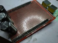
very intuitive use of the PCB, without it trying to have them secure and positioned to solder the wires is some challenge.
I have tried flattening and bending the pins on the chip directly down to solder them together without wires, works ok but kind of messy and easy to break a pin.
I have tried flattening and bending the pins on the chip directly down to solder them together without wires, works ok but kind of messy and easy to break a pin.
The two rows of DACs in the picture are positive and negative phases so this DAC's already running balanced at the front end. I agree it would be better to dedicate each DAC to just one channel but that will have to wait until I install a CPU to pre-process the I2S. Fortunately a dev board for the LPC55S69 is on its way - this has the benefit of 8 I2S in/out ports.
@laserscrape - in the past I tried direct stacking of chips by bending pins down and using solder to bridge across any gaps. It was a bit unreliable in that its quite hard to see when there's a solder joint in place but at least a quick check with a multimeter between top and bottom can reveal continuity. Holding the chips aligned with each other is tricky too without wires mechanically securing the DACs - perhaps I'll experiment with using thick PSU wires as an alignment aid....
Initially I did listening with headphones on this DAC (so far nameless, any suggestions?) but once I got it hooked up to speakers it became apparent its more transparent in the mids than my hacked lingDAC but the bass is soggy. This is going to be because I'm only using a few 10s of thousand uFs on the rails.....
Just my 0-30V 3A adjustable bench supply. Which doesn't have too much going for it other than its not a switcher
Having added a large number of 15,000uF caps to these DACs I'm quite content with the bass now. Not sure how practical 1F of capacitance is in practice though....
Having added a large number of 15,000uF caps to these DACs I'm quite content with the bass now. Not sure how practical 1F of capacitance is in practice though....
There is this strange anonymous post trashing these designs: Misconceptions about multibit superiority - tda1387
The amount of nonsense makes me think the author is one of two things, or a company/business person worried about the idea of dirt cheap but high performing DAC's spreading or someone with a personal vendetta.
The amount of nonsense makes me think the author is one of two things, or a company/business person worried about the idea of dirt cheap but high performing DAC's spreading or someone with a personal vendetta.
...someone with a personal vendetta.
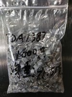
Haven't visited it as google's permanently barred here but a bag of 1000 DAC chips says it's @hollowman
Attachments
@laserscrape - about the impedance of a normal cap in parallel with supercaps. Yes it brings down the impedance but only at higher frequencies - at LF the lower ESR of the normal 'lytic is in series with its capacitance (which is much, much smaller than the supercap's).
I played around with supercaps a few years ago and eventually abandoned them - they give far too much capacitance (in relation to their ESR) to be really useful, not to mention their low working voltage. Incidentally even though 2.7V is below the minimum recommended working voltage for the TDA1387 they still work fine there, but deliver lower current.
I played around with supercaps a few years ago and eventually abandoned them - they give far too much capacitance (in relation to their ESR) to be really useful, not to mention their low working voltage. Incidentally even though 2.7V is below the minimum recommended working voltage for the TDA1387 they still work fine there, but deliver lower current.
I use LT3045 in the supply, It was noted big caps on the output reduce bandwidth of this reg, some said it sounded worse with only a few hundred uf.
Adding a few thousand definitely helped a bit here, there were already a variety of large film caps on the output per markw4's suggestion which could be playing a part.
Still only a micro-fraction of the amount you used so curious to see how much more improvement can be gained.
Adding a few thousand definitely helped a bit here, there were already a variety of large film caps on the output per markw4's suggestion which could be playing a part.
Still only a micro-fraction of the amount you used so curious to see how much more improvement can be gained.
I'm still unclear of the theory behind fitting film caps in parallel with large amounts of electrolytic capacitance. As I see it film caps do have low ESR but given their relatively low capacitance (compared to the 'lytics) the lower ESR only makes a difference at higher frequencies. A film cap with lead spacing of say 25mm or more is also going to have a lot more ESL than the 'lytics so becomes inductive before the 'lytics.
Yes, adding lots of C to the output of regs directly is potentially problematic - I prefer to use a series L between a reg and a C.
Yes, adding lots of C to the output of regs directly is potentially problematic - I prefer to use a series L between a reg and a C.
- Home
- Source & Line
- Digital Line Level
- lingDAC - cost effective RBCD multibit DAC design