Actually, sometimes you can.
On page 4 of this application note one can see what it says about stability of an opamp and output cap with no resistor for an AVCC supply for ESS Sabre DACs: http://www.esstech.com/files/4514/4095/4306/Application_Note_Component_Selection_and_PCB_Layout.pdf
babolcs: You should have read the application note already before agreeing it can't be done. To be a good designer you have to do your homework. Right?
After seeing that it actually can be done in some cases, can either of you guys now explain how it can be possible in terms of loop gain and phase shift?
For convenience I will attach a copy of the page below.
Dear Mark
Thank you for your ideas. Although I haven’t read this but my intention was the following:
- Although it adds some noise to the output but with the cap it acts as a filter so the noise is reduced by frequency.
- it reduces the starting current peak for opa1 and 2
- and as you have written regarding the offset starting circuit that it should work in all the cases. So we can’tafford that in some cases it will oscillate - which likelihood can be definitely reduced with this R.
Anyway our panel contains a 4.7 ohms too. The value can be considered.
Besides that I can’t wait that others are doing my homework. If someone intend to help than the common work can speed up the whole process. If no one participates I will check alone if my idea works or not. Maybe I will run into some deadend street which can be avoided whit the common work and shared experiences. But no expectation from my side. And I really thankful for all contributions.
Or did I misunderstood the philosophy of this whole site?
Sorry if I see wrong. And really thanks for your comments till now.
Sz
Btw.
I know that still there is a task(even if the circuit works well) I have to find a protection circuit which prevents the Dac from overvoltage if somehow It starts to oscillate. This can be a simple shottcky to dac vcc. Or I have to calculate maybe the output r and cap Can also solve this issue.
I know that still there is a task(even if the circuit works well) I have to find a protection circuit which prevents the Dac from overvoltage if somehow It starts to oscillate. This can be a simple shottcky to dac vcc. Or I have to calculate maybe the output r and cap Can also solve this issue.
babolcs, I can't speak for others, but as for myself I am happy to help people who are willing to do a fair amount of the work. I am also willing to help people learn if they would like to learn. I am not necessarily willing do a lot of work for someone who doesn't seem interested enough in learning or working.
I guess I was disappointed that you came to the other thread expressing interest in make good DACs and now I find out you seemingly did not bother to read the information you need to read to understand why we do some things they way we do. After all, we have been talking about the ESS opamp circuit for some time by now. To make sure you do know now, it does not use a resistor before the cap. Exact same thing for the diagram number 4 you mentioned, it uses a cap without a resistor. You didn't notice that? If you did notice any of that then how could you say it will necessarily be unstable?
Maybe it would help if you would be willing to explain a little more about your electronics background. If you are an engineer with some experience you would probably know about control theory for stability. If a circuit has a cap and is stable that implies certain things about the cap and or the circuit, right? If I need to explain I would do so happily, but please don't tell me I am wrong if you don't really know.
babolcs, I can't speak for others, but as for myself I am happy to help people who are willing to do a fair amount of the work. I am also willing to help people learn if they would like to learn. I am not necessarily willing do a lot of work for someone who doesn't seem interested enough in learning or working.
I guess I was disappointed that you came to the other thread expressing interest in make good DACs and now I find out you seemingly did not bother to read the information you need to read to understand why we do some things they way we do. After all, we have been talking about the ESS opamp circuit for some time by now. To make sure you do know now, it does not use a resistor before the cap. Exact same thing for the diagram number 4 you mentioned, it uses a cap without a resistor. You didn't notice that? If you did notice any of that then how could you say it will necessarily be unstable?
Maybe it would help if you would be willing to explain a little more about your electronics background. If you are an engineer with some experience you would probably know about control theory for stability. If a circuit has a cap and is stable that implies certain things about the cap and or the circuit, right? If I need to explain I would do so happily, but please don't tell me I am wrong if you don't really know.
Mark I haven’t told you are wrong. I just stated I had different considerations.
I graduated 25 years ago as engineer but during my life I didn’t used the things I learnt. Now getting the kids older I thought I refresh a littlebit myself.
Still I think that this forum is a common work. Since you started consodering in the other thread the battery based solution I thought I go on a different way.
Anyway this solution can be independent not only ESS related.
Still I state I do not expect that you work instead of me.
Besides that it is not a workplace. If we can handle everything here as fun than it is ok. But if we hit and hurt each other with words than it is not ok anymore.
My intention Was not that at all.
Okay, that works for me.
Aluminum electrolytic caps typically start looking inductive up around 100kHz. Special caps such as made for switching supplies go higher before that happens. A high speed opamp doesn't necessarily care too much if a cap is connected to the output at a very low frequency, just so long as it doesn't add phase shift at high frequencies where the opamps own phase shift is increasing. For that reason a big electrolytic on the output of an opamp may be stable. On the other hand, we have to choose bypass caps for fast opamps that look like caps up to many MHz. We typically use ceramics for that part of the frequency range. Connecting a cap that does add a lot of phase shift at high frequencies is another matter, in the absence of mitigating factors it would be likely to cause oscillation if connected to the output of another opamp. Of course, if there is resistance and inductance between the opamp output and the high frequency cap, that may change the amount of phase shift relative to if it were connected directly at the output. So, depending on the layout between the opamp acting as a power supply and the other opamp acting as a load, parasitic effects in the wiring can affect whether or not the supply opamp will be stable.
Aluminum electrolytic caps typically start looking inductive up around 100kHz. Special caps such as made for switching supplies go higher before that happens. A high speed opamp doesn't necessarily care too much if a cap is connected to the output at a very low frequency, just so long as it doesn't add phase shift at high frequencies where the opamps own phase shift is increasing. For that reason a big electrolytic on the output of an opamp may be stable. On the other hand, we have to choose bypass caps for fast opamps that look like caps up to many MHz. We typically use ceramics for that part of the frequency range. Connecting a cap that does add a lot of phase shift at high frequencies is another matter, in the absence of mitigating factors it would be likely to cause oscillation if connected to the output of another opamp. Of course, if there is resistance and inductance between the opamp output and the high frequency cap, that may change the amount of phase shift relative to if it were connected directly at the output. So, depending on the layout between the opamp acting as a power supply and the other opamp acting as a load, parasitic effects in the wiring can affect whether or not the supply opamp will be stable.
Last edited:
first build
Mark,
it's fine with me too.
Meanwhile I built the very first version without additonal caps.
At least it started.
1)
I checked with 6pcs 5532 (only 1 side) in OPA1 pos and TL081 in OPA2 pos. (this was fixed) I also checked with an OPA2134. Here I experienced some instaility (Currently I don't have a scope so could measure 16mV AC accross a CAP -so likely it oscillated.), so I put a 10uF tantallum next to the LEDs.
2)
with the tantallum i Retested and in 2 cases with the NE5532 it hasn't started. (wiht others yes)
3)
The DC stability seemed quite OK. VCC was varied from 9V till 19V. and measured the output of OPA1 and OPA2. (currently I put 560ohms instead of 510) so the output of OPA1 should have been alomst 12V.
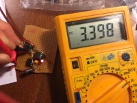
But between the normal range (from ~13,2V for 5532 and ~13,8V for the 2134 the OPA1 output changed between 11,983 and 12,009 and OPA2 output remaind stable 3,398V.
(Side comment: Naturally at very low OPA1 VCC (9V) the output of OPA1 can't reached the required value (was ~7.8), but still the OPA2 output was quite stable (3,248).)
I tried to measured some thermal stability with a very simple way: heated 1 leg of LED and experienced a negative coeficient. I measured 20mV decrease for 20C increase (likely it was not punctual enough, since it should be 2mV/1Celsius/LED.
As I mentioned I don't have a scope currently so I can't tell exactly what noise or oscillation AC is on the output. Definitely I will buy something") and built a noise amplifier.Afther that I can play more with the filtering caps - how it behaves for different scenarios - considering the different CAP behaviours you described.
and built a noise amplifier.Afther that I can play more with the filtering caps - how it behaves for different scenarios - considering the different CAP behaviours you described.
Sz.
Okay, that works for me.
Aluminum electrolytic caps typically start looking inductive up around 100kHz. Special caps such as made for switching supplies go higher before that happens. A high speed opamp doesn't necessarily care too much if a cap is connected to the output at a very low frequency, just so long as it doesn't add phase shift at high frequencies where the opamps own phase shift is increasing. For that reason a big electrolytic on the output of an opamp may be stable. On the other hand, we have to choose bypass caps for fast opamps that look like caps up to many MHz. We typically use ceramics for that part of the frequency range. Connecting a cap that does add a lot of phase shift at high frequencies is another matter, in the absence of mitigating factors it would be likely to cause oscillation if connected to the output of another opamp. Of course, if there is resistance and inductance between the opamp output and the high frequency cap, that may change the amount of phase shift relative to if it were connected directly at the output. So, depending on the layout between the opamp acting as a power supply and the other opamp acting as a load, parasitic effects in the wiring can affect whether or not the supply opamp will be stable.
Mark,
it's fine with me too.
Meanwhile I built the very first version without additonal caps.
At least it started.
1)
I checked with 6pcs 5532 (only 1 side) in OPA1 pos and TL081 in OPA2 pos. (this was fixed) I also checked with an OPA2134. Here I experienced some instaility (Currently I don't have a scope so could measure 16mV AC accross a CAP -so likely it oscillated.), so I put a 10uF tantallum next to the LEDs.
2)
with the tantallum i Retested and in 2 cases with the NE5532 it hasn't started. (wiht others yes)
3)
The DC stability seemed quite OK. VCC was varied from 9V till 19V. and measured the output of OPA1 and OPA2. (currently I put 560ohms instead of 510) so the output of OPA1 should have been alomst 12V.
But between the normal range (from ~13,2V for 5532 and ~13,8V for the 2134 the OPA1 output changed between 11,983 and 12,009 and OPA2 output remaind stable 3,398V.
(Side comment: Naturally at very low OPA1 VCC (9V) the output of OPA1 can't reached the required value (was ~7.8), but still the OPA2 output was quite stable (3,248).)
I tried to measured some thermal stability with a very simple way: heated 1 leg of LED and experienced a negative coeficient. I measured 20mV decrease for 20C increase (likely it was not punctual enough, since it should be 2mV/1Celsius/LED.
As I mentioned I don't have a scope currently so I can't tell exactly what noise or oscillation AC is on the output. Definitely I will buy something
and built a noise amplifier.Afther that I can play more with the filtering caps - how it behaves for different scenarios - considering the different CAP behaviours you described.Sz.
Attachments
Last edited:
I devided the output to half, so I could see 1 more digit.
and between the operating input voltage range (13-19V) I even can't see 0,1mV change.
so the input stability is really nice.
I replaced the LEDs with 1kOhm in that case the temparature instability derives only from the FET, which is smaller then the LEDs. I'm considering and checking how can it be as much close to 0 as possible.
And FET noise is higher than 1K resistor noise
This is why to use the 2sk170 which has 0.95nV/sqrt(Hz) noise
the 1K is roughly 4,5nV.
Since they are parallel from noise point of view it will be <4,5nV.
If we would like to use it for DAC Vref and targets the -120dB and we calculate for 1Hz-100kHz it should be below 2.5nV for the whole circuit
(if I calculate well)
without any additional filter this noise transferred to the output.
A capacitor can reduce it.
Just a side comment, besides that
my first goal to built a stable non oscillating, and always starting circuit.
2nd step would be to optimize for noise
3rd step add safety part to maximize the output to 3.3V without increasing the noise - for the case if oscillation occurs somehow.
But anyway thanks for the comment.
Szabolcs
PS. meanwhile I added a small simple amplifier with 1000 gain, and it likely do not oscillate even without the CAP. I can measure 4mV there.
But i have to do it more sophisticated, because this amplifier circuit has higher noise itself.
(2 stages with smaller resistors, limit in freq, etc...)
But i have to do it more sophisticated, because this amplifier circuit has higher noise itself.
(2 stages with smaller resistors, limit in freq, etc...)
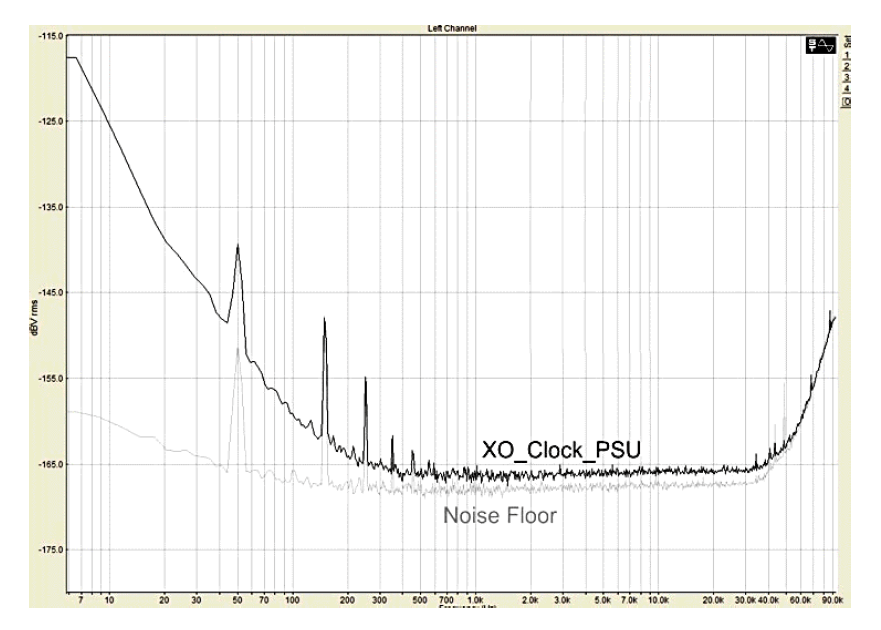
Someone have proposed similar idea many years ago. The FLEA regulator is similar to yours. It even has capacitance multiplier & pre-reg at the input plus LPF at the Vref.
The test figure.
As the noise floor going up from 40Khz, we don't know the real performance of the FLEA at higher freq.
The test figure.
As the noise floor going up from 40Khz, we don't know the real performance of the FLEA at higher freq.
Last edited:
Flea idea looks good. As far as HF goes, one could use an LT3045 as buffer. Problem with them is on the low end, their 1/f corner is rather high to be optimal for audio.
At very LF, LTC6655 has a very low 1/f corner.
I would still like to see what using an LT3045 as a buffer for LTC6655 would look like. It is suggested in the LT3045 data sheet and seems much more suitable for audio than the usual LT3045 stuff so many people seem to be so excited about for audio.
Might be worth getting one of these things and modding it use an LT6655 reference: Low Noise LT3042 Linear Regulator Power Supply Board DC Converter Overvoltage | eBay At least the PCB layout is better than some of the LT3045 modules. We would need somebody with suitable measurement equipment though.
Last edited:
Problem with them is on the low end, their 1/f corner is rather high to be optimal for audio.
Increase the bypass cap at R-set is the only way. I used 220uf and I can hear the difference at LF.
Someone have proposed similar idea many years ago. The FLEA regulator is similar to yours. It even has capacitance multiplier & pre-reg at the input plus LPF at the Vref.
The test figure.
As the noise floor going up from 40Khz, we don't know the real performance of the FLEA at higher freq.
Dear Canvas,
Thanks for your comment. It definitely worth to consider some ideas from it.
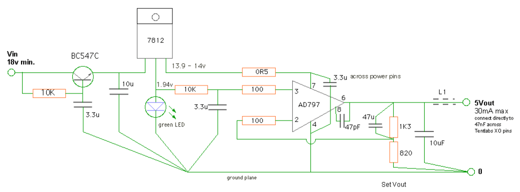
The cap multiplicator and the filtering around the base source (LED) here.
BUT obviously the main difference, that in my circuit the 1st stage is an OPA too. and the LED is powered from the already filtered output of OPA1. Definitely the OPA has much better performance over a quite wide range of frequency compared to the 78XX/LM317.
And in addition I don't know how noisy the common point of these REGs are.
(Although I suppose it is low, since the guy who suggested the circuit definitely put the LED consciously there.)
(Now it is morning in HU and just wanted to have a quick look, so don't have time to check in details)
The output noise has 2 main sources: the VREF and the Power rail (and definitely much more, the internal noise of OPA/REG, the capacitors, the resistors, etc.)
In this original circuit (let's call it 00Reg -thanks for the inspiration to give a name) nothing on the original power rail, just the OPA1.
As Mark wrote in the next post LT3045 can be considered as first stage.
OR the suggested LTC6655 can be used instead of the LED (noise - worth to compare of it with the earlier suggested Resistor solution - increasing the current of the Current source and lowering it to somewhere 470ohm. Which has roughly 3nV noise )
The nice thing here is that really there are a lot of opportunities and several can result something good.
I would stick to the original 2 OPA concept - considering all the suggested ideas.
Naturally someone can work on the 3045+OPA or 3045+LTC6655 ideas.
Thanks a lot,
Sz.
Last edited:
babolcs,
Well, I'm looking forward to your result. BTW, I don't think LTC6655 is better. There are always trade-offs. LED has lowest noise, but it will drift with temperature. On the other hand, anything with bandgap reference will be noisy to some extend. I'd stick with LED rather than chip Vrefs.
Poting
Well, I'm looking forward to your result. BTW, I don't think LTC6655 is better. There are always trade-offs. LED has lowest noise, but it will drift with temperature. On the other hand, anything with bandgap reference will be noisy to some extend. I'd stick with LED rather than chip Vrefs.
Poting
babolcs,
Well, I'm looking forward to your result. BTW, I don't think LTC6655 is better. There are always trade-offs. LED has lowest noise, but it will drift with temperature. On the other hand, anything with bandgap reference will be noisy to some extend. I'd stick with LED rather than chip Vrefs.
Poting
Thanks for the confirmation. I found another thread where there are nice considerations for LED noise. In the evening I will add th link here. It is below 0,5nV.
@Mark could you please confirm how big problem the temp drift for DAC?
As I have seen for LED generally 2mV/C so 4mV for the 2 LEDs. Thanks Sz
A little slow temp drift for a DAC should not a problem so long as both channels are using the same reference, at least for a DIY DAC. However, each channel should have its own output buffer.
A commercial or professional DAC would need to stay at calibrated volume levels, since any volume level drift could potentially be a problem. Say for example, if two stereo DACs where to be used to make a 4-channel (or maybe 5.1, or 7.1) surround system then drift in one DAC but not another could cause channel balance to drift.
A commercial or professional DAC would need to stay at calibrated volume levels, since any volume level drift could potentially be a problem. Say for example, if two stereo DACs where to be used to make a 4-channel (or maybe 5.1, or 7.1) surround system then drift in one DAC but not another could cause channel balance to drift.
A little slow temp drift for a DAC should not a problem so long as both channels are using the same reference, at least for a DIY DAC. However, each channel should have its own output buffer.
A commercial or professional DAC would need to stay at calibrated volume levels, since any volume level drift could potentially be a problem. Say for example, if two stereo DACs where to be used to make a 4-channel (or maybe 5.1, or 7.1) surround system then drift in one DAC but not another could cause channel balance to drift.
Yes it is very clear that the opa2 has to be duplicated for the 2 channels.
Room temperature shouldn’t be changed more then 10 Celsius. (I’m not speaking about Salas shunt in the same box
) so it is roughly 40mV. 1%. As you wrote it shouldn’t be problem at home. Thanks for the info.- Status
- This old topic is closed. If you want to reopen this topic, contact a moderator using the "Report Post" button.
- Home
- Source & Line
- Digital Line Level
- OPA based Ultra Low noise VREF for DAC