The unit in question is a Creek CD-60 compact disc player from the early 1990s (designed in 1991). It uses the classic Philips chipset (SAA7220/TDA1541).
In the following schematic excerpt from the CD-60's I/V section, what's Creek doing with that LM78L05 tied into the OPA2604 inverting input pin (pin 6)?
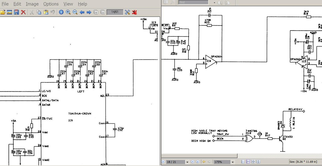
Methinks maybe some sort of biasing (as often the case with discrete I/V's) ... but never seen an opamp biased this way?
Anyone know?
In the following schematic excerpt from the CD-60's I/V section, what's Creek doing with that LM78L05 tied into the OPA2604 inverting input pin (pin 6)?
Methinks maybe some sort of biasing (as often the case with discrete I/V's) ... but never seen an opamp biased this way?
Anyone know?
First, remember that the 1541 goes from 0 to -4mA, current sink.
That 7805 regulator and associated resistors (and LPF) injects a fairly clean 2mA current to null the TDA1541 midscale current (-2mA). 5V / 2.4K = 2.08mA
This way the opamp operates in a better condition, that is, with 0V output when the dac is at midscale.
That 7805 regulator and associated resistors (and LPF) injects a fairly clean 2mA current to null the TDA1541 midscale current (-2mA). 5V / 2.4K = 2.08mA
This way the opamp operates in a better condition, that is, with 0V output when the dac is at midscale.
Hmm....
In other words, did Creek design an ad hoc current injector specifically for the OPA2604?
How much (if at all) should one tweak that 7805 injection current if the stock opamp is replaced with another model.First, remember that the 1541 goes from 0 to -4mA, current sink.
That 7805 regulator and associated resistors (and LPF) injects a fairly clean 2mA current to null the TDA1541 midscale current (-2mA). 5V / 2.4K = 2.08mA
This way the opamp operates in a better condition, that is, with 0V output when the dac is at midscale.
In other words, did Creek design an ad hoc current injector specifically for the OPA2604?
In other words, did Creek design an ad hoc current injector specifically for the OPA2604?
Nope. That should do the job for any opamp. You could change the first resistor to a trimpot, say 1K5. Then you can trim for 0V at the output of the opamp.
You could also make sure the caps are good quality and effective at high frequencies. The regulator has poor HF line rejection.
Well, sorta...That should do the job for any opamp.
It depends on the input impedance of the opamp in inverting mode. It should be very low, but more importantly, it should remain low above audio frequencies. It would be desirable to have it flat into the MHz. That will likely be the case with modern high speed opamps such as the THS4031.
Last edited:
Hard to understand why they created a specially regulated 5V supply for this purpose. They wanted to inject a current, so it must follow that the higher the source impedance, the better. There will already be regulated rails for the opamps (probably 15V) so why not run direct from them? From 15V that would make a 3X higher source impedance source.
Hard to understand why they created a specially regulated 5V supply for this purpose. They wanted to inject a current, so it must follow that the higher the source impedance, the better. There will already be regulated rails for the opamps (probably 15V) so why not run direct from them? From 15V that would make a 3X higher source impedance source.
May I ask why higher source impedance is better here? And, why a 15V rail will provide 3X hiehr source impedance? Thanks
Poting
The ideal current source has infinite output impedance. This means the current does not vary with output voltage. Just as an ideal voltage source has zero output impedance, meaning no variation in voltage with output current.
If the output voltage doesn't vary then this won't really matter, but here the output voltage will change due to the extreme rise/fall times coming out of the DAC. The opamp's virtual ground cannot keep up so while the opamp is slewing there will be a non-zero voltage at its -ve input. Hence with a varying output voltage there won't be a constant current through the biassing R (R17 here). A higher source impedance means there's less variation of current with output voltage.
The R here is 2k4 but if we ran from 15V we could use (say) 7k5 to get the same (2mA) current. That's around 3X higher source impedance.
Hard to understand why they created a specially regulated 5V supply for this purpose...There will already be regulated rails for the opamps (probably 15V) so why not run direct from them? From 15V that would make a 3X higher source impedance source.
Agreed. I can only think that, perhaps, they were concerned about crosstalk coupling from the 15V supply rails to the op-amp's inverting inputs.
Last edited:
Pedja used a one jfet CCS for this. He started with the 2SK170 and later switched to BF245A.
Looking at the datasheet: https://www.nxp.com/docs/en/data-sheet/BF245A-B-C.pdf
The zero tempco current of the BF245A is under 1mA. Not ideal (we would like zero tempco at 2mA). But much better than the 2SK170, which is closer to 8mA IIRC.
Looking at the datasheet: https://www.nxp.com/docs/en/data-sheet/BF245A-B-C.pdf
The zero tempco current of the BF245A is under 1mA. Not ideal (we would like zero tempco at 2mA). But much better than the 2SK170, which is closer to 8mA IIRC.
...though the solution would then be to use a 12V regulator, not a 5V one...
Good point.
- Status
- This old topic is closed. If you want to reopen this topic, contact a moderator using the "Report Post" button.
- Home
- Source & Line
- Digital Line Level
- What's in the Creek CD-60 i/v section?