Hi
Where do you connect the PANASONIC 1000µf16v ?
Thanks
Serge
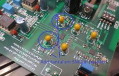
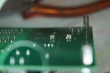
As Mark said, I replaced the two 4.7uF tantalum bead caps (orange blobs) that are on the outputs of the two LT3042 - one reg for each AVCC. Those caps measured 0.7 ESR which is too high according to LT datasheet. I also increased the Cset cap by adding a second smd tantalum in parallel for a total of ~15uF. I'm still experimenting with that too. (see attached photo, note that many of the components in it are different to the boards we have - e.g. some smd ceramics are now polarised caps, tantalum I think)
Most ldo's like to have more capacitance before (input) than after (output) so it's common to increase both input and output at the same time. TI TPA7*** ldo's actually start mildly oscillating and sound bad if the input cap is not "bigger" than the output.
However, the design of the LT3042 is quite different from most other ldo (its error amplifier is always in unity gain, the voltage reference is actually a current reference, etc) and it seems that the "matching input and output caps guideline" might not apply, especially because this DAC board has a CCS+shunt pre-regulator and reasonably short traces into the regulators. However, don't take it from me that this is a worked solution please - need more time to experiment. But please try it and see what you think. You can listen for any change in frequency response such as a new resonance in the upper mids/highs, listen for any grainy roughness in female vocals, any strange sounding percussion, jazz brush, piano, etc.
The LT3042 is not oscillating with such a large output cap - I checked thermals and voltages and everything was normal so I didn't bother checking on my ancient scope. Nonetheless, the graph below, on the right hand side, shows an increasing upper frequency PSRR peak with 22uF, and that suggests that a bigger cap might create a trough in PSRR in very high audio frequencies and that trough might manifest itself in odd behaviour. I'm not sure because this ldo is a different design and I haven't seen any SIMs for it.
An externally hosted image should be here but it was not working when we last tested it.
I'd also recommend something like Rubycon ZLH 6.3V 1800uF instead of Panasonic FR because IIRC ZLH comes in a 6x20 package that would fit perfectly and has an ESR significantly below the regulator's requirements. I'm out of stock of these but I'm going shopping on the way home from work and hope to find some in the electronics street here. An 1800uF cap with less than 10mA of ripple equates to low uV of ripple - it mitigates the ability of the DAC chip to modulate the regulator. It's kinda like the effect of lowering output impedance. Unfortunately, electrolytics are not the best - might change the tonal balance for example - but given space and the desire for an easy simple upgrade, they might do just fine if, like me, you don't want to replace the LT3042 with super caps etc.
Attachments
Last edited:
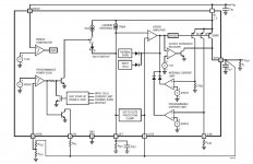
At lunch I had another look at the datasheet to see what is internally and externally connected to the output - see attached - it does not show detail e.g."Note 7: SET and OUTS pins are clamped using diodes and two 25Ω series resistors" but it suffices.
Page 13 "OUTS (Pin 9): Output Sense. This pin is the noninverting input to the error amplifier. For optimal transient performance and load regulation, Kelvin connect OUTS directly to the output capacitor and the load. Also, tie the GND connections of the output capacitor and the SET pin capacitor directly together. Moreover, place the input and output capacitors (and their GND connections) very close together."
Also noteworthy re cap size on page 22 because OUTS is connected to out and of course the output cap " To protect the LT3042’s low noise error amplifier, the SET to-OUTS protection clamp limits the maximum voltage between SET and OUTS with a maximum DC current of 20mA through the clamp.... ...to limit the transient current flowing through these clamps during a transient fault condition, limit the maximum value of the SET pin capacitor (CSET) to 22μF." Fault condition being an output short or something close to it?
However, none of this suggests to me that the output capacitor needs to be limited in size.
Re stability, on page 17 "The minimum input capacitance needed to stabilize the application also varies with the output capacitance as well as the load current. Placing additional capacitance on the LT3042’s output helps. However, this requires significantly more capacitance compared to additional input bypassing."
So I don't see any reason a big cap can't be used on the output.
And no reason for a big input cap, p12, "While a 4.7μF input bypass capacitor generally suffices, applications with large load transients may require higher input capacitance to prevent input supply droop." This DAC creates small load transients and the regulator is preceeded by a CCS+shunt so supply droop isn't a significant factor.
If Cset is large, then start up is slow, so inrush current is not an issue either. ANY huge cap size on output is possible? Of course, it might colour the sound heavily, but....
Attachments
Last edited:
Hi,
Definitely the vocals were too forward and aggressive and the sound stage was "not right". I'm sure you have some tracks that you know intimately so you know when they don't sound right. It's hard to describe when the sound is off true but doesn't have obvious harmonic or IM distortion or noise or... maybe has a little of everything so it's off.... not exactly jitter mush either but that's the closest analogy. The LME49720 have amazing micro-detail retrieval and that gives a slightly clinical sound. OPA2132PA are sweeter and warmer. AD8599 sound lovely but they get very hot. JRC2114 are well rounded but a bit dull. I still think OPA1612 are the best all round sound.
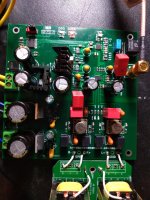
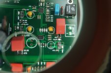
I was trying to work through a Taguchi house of quality thing where I modify the part I think is most likely having the greatest effect but I missed one - the output cap on the 1.8V LT3042 that feeds the SA8804 (and ES dac too? I haven't checked) was one 4.7uF tantalum and it wasn't enough. I added a 22uF SMD X7R ceramic on the underside in parallel with the tant and that did it. I was, of course, surprised because I didn't think it would be critical but hey ho, live and learn. Of course, this is after having done everything else. And I am now using 6.3V Rubycon YXG 2,700uF (10mm x28) caps on AVCC and I've removed the extra tantalum on Cset and using 4.7uF Wima in parallel with the original 4.7uF smd tant.
I'm gonna let the new caps burn in overnight and listen again tomorrow evening.
I also added a 4.7uF tant at Cset for the 3.3V digital supply and this is the limit because it seems this slows the start up enough that once or twice I get both lock and dsd LEDs flashing. Switch off/on and it's no problem. I could try to enable fast start up... The DAC is also sensitive to spikes on the mains, momentarily losing lock when something else turns on/off, such as the soldering station or whatever. My main hi-fi has isolation and mains filtering but this is in the spare room with crap quality mains.
Definitely the vocals were too forward and aggressive and the sound stage was "not right". I'm sure you have some tracks that you know intimately so you know when they don't sound right. It's hard to describe when the sound is off true but doesn't have obvious harmonic or IM distortion or noise or... maybe has a little of everything so it's off.... not exactly jitter mush either but that's the closest analogy. The LME49720 have amazing micro-detail retrieval and that gives a slightly clinical sound. OPA2132PA are sweeter and warmer. AD8599 sound lovely but they get very hot. JRC2114 are well rounded but a bit dull. I still think OPA1612 are the best all round sound.
I was trying to work through a Taguchi house of quality thing where I modify the part I think is most likely having the greatest effect but I missed one - the output cap on the 1.8V LT3042 that feeds the SA8804 (and ES dac too? I haven't checked) was one 4.7uF tantalum and it wasn't enough. I added a 22uF SMD X7R ceramic on the underside in parallel with the tant and that did it. I was, of course, surprised because I didn't think it would be critical but hey ho, live and learn. Of course, this is after having done everything else. And I am now using 6.3V Rubycon YXG 2,700uF (10mm x28) caps on AVCC and I've removed the extra tantalum on Cset and using 4.7uF Wima in parallel with the original 4.7uF smd tant.
I'm gonna let the new caps burn in overnight and listen again tomorrow evening.
I also added a 4.7uF tant at Cset for the 3.3V digital supply and this is the limit because it seems this slows the start up enough that once or twice I get both lock and dsd LEDs flashing. Switch off/on and it's no problem. I could try to enable fast start up... The DAC is also sensitive to spikes on the mains, momentarily losing lock when something else turns on/off, such as the soldering station or whatever. My main hi-fi has isolation and mains filtering but this is in the spare room with crap quality mains.
Last edited:
If LME49720 sound as you say, it is an indications of additional problems with the dac, IME. Little bits of distortion here and there still remaining. Also, a transformer may not be enough to remove remaining RF and HF junk that should be filtered out by a full output stage. So far, you probably only have one or maybe two poles of analog filtering. Some transformers can pass some or a lot of that HF junk to the output, depends.
Regarding slow start of LT304x, I modded one for fast start and took pictures of how to do it. Did because of a boot problem with one board that needed faster power rise time. Depends if you want to do that type of thing or not, however.
Also, since it is an ES9038Q2M dac in that board, a lot of what we are doing over the 'ES9038Q2M Board' thread is probably applicable here. Power supplies in general, AVCC power, output stage including analog filtering, opamp power bypassing, clocking, clock power, dac register settings, everything matters to get the best sound out of those dac chips.
I have done a lot of work on mine, and I know Allo has put a whole lot of engineering effort into Katana dac, which is based on ES9038Q2M. Since I am a Katana reviewer I know it pretty well too , certainly have done a lot of listening (up to v1.1 so far anyway, still waiting for v1.2 to ship to reviewers).
However, don't know how interested you are in working on dacs, or if you were hoping for more of a "buy it and be done with it" type of solution.
Last edited:
I was hoping to buy it and use it but in fact it needed work because it did not sound nice straight from the box, but that's largely done now - it sounds right regardless of the op amp - I hear the op amp's character, which I know well from previous DAC and headphone amp building. It's not as good as the ES9018 I built, or the dual mono 384KHz NOS DAC but it is actually much better than I thought a Q2M would be and for US$50 + replacement cap cost, it's a good deal. The parts, the PCB, the design - it's all good except for almost all of the through hole caps and the 317/337 implementation. Fix those and it's a winner. When I get a final set up, I'll post the details so anyone else who buys one can fix theirs too.
Last edited:
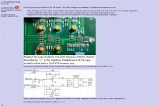
So it's just four caps needed to "fix" the board - the other changes are tweaking. It's simple and inexpensive to do:
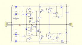
And here's my preferred output circuit. Transformer leakage is quite low so it's only filtering above 100KHz or so.
Work is getting increasingly busy so I'm signing off DiyAudio for a while. Apologies in advance if you want to ask a question etc.
- buy two Rubycon YXG 2700uF 6.3V 10x28mm electrolytic capacitors and two (any brand) 22uF X7R 1210 16V or 25V ceramic capacitors.
- on the underside of the board, solder on the 22uF caps in parallel with the 4.7uF yellow blob tantalum caps
- remove two 4.7uF yellow blob tantalum caps and fit the Rubycon in the their place paying attention to polarity.
An externally hosted image should be here but it was not working when we last tested it.
And here's my preferred output circuit. Transformer leakage is quite low so it's only filtering above 100KHz or so.
An externally hosted image should be here but it was not working when we last tested it.
Work is getting increasingly busy so I'm signing off DiyAudio for a while. Apologies in advance if you want to ask a question etc.
Last edited:
Notes on tweaking this board
Improving op amp power regulation has a strong effect
removing the op amp sockets and improving psu decoupling has a stronger than usual effect
Lt3042 have PG pins floating and it is extremely difficult to change this to enable fast start up. I didn't manage to do it.
As a result, the 3.3V digital supply will only tolerate an extra 1uF at Cset and it must be smd, e.g. pps film. A box cap of 1uF causes start up issues, smd pps does not
Lt3042 Cset caps affect sound and film sound best.
Last edited:
If that's a 3042 and not the larger 3045, then props to you! That's some very delicate and difficult skills - well done. I find perfectly proportioned gobs of solder to be strangely delightful ") I can manage the 3045 on a separate PCB but I know my skills aren't up to the 3042 in it's crowded location on this DAC. I did it to convert a 3.3V to 12V with 22uF Cset. Without fast start up, it takes seconds.
I can manage the 3045 on a separate PCB but I know my skills aren't up to the 3042 in it's crowded location on this DAC. I did it to convert a 3.3V to 12V with 22uF Cset. Without fast start up, it takes seconds.
I can manage the 3045 on a separate PCB but I know my skills aren't up to the 3042 in it's crowded location on this DAC. I did it to convert a 3.3V to 12V with 22uF Cset. Without fast start up, it takes seconds.An externally hosted image should be here but it was not working when we last tested it.
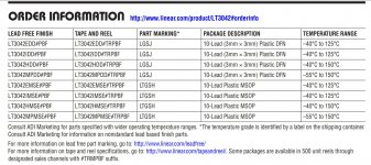
It's an LT3042. See part numbers on the chip and on the board. That's the branding code on the chip for a '42.
It always surprises me some of the stuff that is actually doable by hand. Yet, somehow it works out.
It always surprises me some of the stuff that is actually doable by hand. Yet, somehow it works out.
Attachments
Last edited:
It's an LT3042. See part numbers on the chip and on the board. That's the branding code on the chip for a '42.
It always surprises me some of the stuff that is actually doable by hand. Yet, somehow it works out.
Sure, it works... for you!
I don't care to think of all the gear I've trashed because my ego exceeded my skills.
Last edited:
Thank you ,Nanoloop,fore all the efford of tweaking this board
When I finish my GU-50 monoblock project with bias automation,I wil go on with this dac.
The thing that is not clear for me, is how you fixed the op amp power supply?
On my board there is no LM317 fore the digital supply.
When I finish my GU-50 monoblock project with bias automation,I wil go on with this dac.
The thing that is not clear for me, is how you fixed the op amp power supply?
On my board there is no LM317 fore the digital supply.
Last edited:
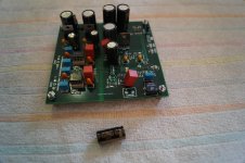
Today i have got 2700uF 6,3v rubycons.
Put them in and did the rest of the mods.
Plugt it in and it sounds nice.
Big sound not harsch and plenty of base.
What to do next,is making the opamp I/V powered external.
Put them in and did the rest of the mods.
Plugt it in and it sounds nice.
Big sound not harsch and plenty of base.
What to do next,is making the opamp I/V powered external.
Attachments
- Status
- This old topic is closed. If you want to reopen this topic, contact a moderator using the "Report Post" button.
- Home
- Source & Line
- Digital Line Level
- My ES9038Q2M DAC board