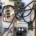
I hooked it all up for the first time: (temp) power supplies, DAC and I2S connection from HifiBerry Digit+ Pro. Can’t really judge the sound yet; couldn’t connect it to my proper set yet. When the Silent Switchers arrive next week, I’ll hook those up and give it another go.

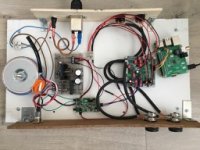
Version 0.1 of this DAC build is ready! It features:
- power (+/- 15V and 3.3V) supplied by the new variable SilentSwitcher, in turn fed by a transformer and PSU, that I recycled from a previous project
- the 9038PRO DAC board
- digital signal supplied by I2S from a HifiBerry Digi+Pro on top of a Raspberry Pi 3B
- separate L/R volume controls
- balanced outputs
I've been listening to it for about a week now. My impression is very positive: the sound has a lot of detail and clarity, with a wide sound stage. Also there is almost no pops/clicks at start-up and shutdown and no noise at all when changing tracks - which was my main annoyance with my previous set-up (Beresford TC-7520SE Caiman, using SPDIF output from the Digi+). I do have to get used to the difference in frequency response. Apparently the Beresford had a very "warm" sound, with more bass, whereas the high level of detail in the higher tones make the 9038 sound more "trebly".
I intend to get a proper oscilloscope soon and publish some measurements on the unit.
Attachments
Last edited:
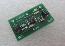
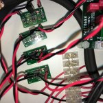
I now equipped each of the 3.3V inputs with its own LT3045 regulator module. See attached pics. Of course it is subjective but to me the sound has really improved. Frequency response of low frequencies is very good now; the balance between low and high is right. And the sound stage is even wider and more detailed. I really like the sound of this DAC! I am hearing things in my good old song collection that I never heard before. ")
Oscilloscope is supposed to arrive coming week. Let's see if the measurements are as good as the sound...
Oscilloscope is supposed to arrive coming week. Let's see if the measurements are as good as the sound...
Attachments
Good to read that the sound quality is getting better. How about the clock on that dac?
Many people find another leap upward in terms of improved sound quality with an ultra-low phase noise clock if the dac doesn't already have one. Crystek 575 is a good and popular choice if looking for 100MHz.
Also, if using LT3045 for AVCC 3.3v power, Cset should be increased to the maximum recommended 22uf. Data sheet has info on recommended dielectric type.
Last edited:
I now equipped each of the 3.3V inputs with its own LT3045 regulator module. See attached pics. Of course it is subjective but to me the sound has really improved. Frequency response of low frequencies is very good now; the balance between low and high is right. And the sound stage is even wider and more detailed. I really like the sound of this DAC! I am hearing things in my good old song collection that I never heard before.
Oscilloscope is supposed to arrive coming week. Let's see if the measurements are as good as the sound...
Just to confirm - each of the four is AVCC_L, AVCC_R, VCCA and DVCC?
I'm currently playing around with a 9018k2m - it's very small so due to space constraints I'm trying to see if I can use 3 regs - first one for both AVCC L & R (some loss of stereo separation is expected), second for VCCA and DVCC (no audible effect from sharing via separate ferrite beads/caps? they have some PSRR so I hope not), and third for the 100MHZ xo.
Looking forward to your scope results
Last edited:
Crystek 575 is a good and popular choice if looking for 100MHz.
Thanks for the suggestion! I have put it on my list.
Cset should be increased to the maximum recommended 22uf.
Could you explain why that is? My secondary goal with this project is to learn more about electrical engineering...
Could you explain why that is?
Increasing Cset reduces low frequency noise. It also increases the time it takes for the output voltage to come up to full value when the power is switched on. For AVCC increased start up time would not be a problem. The reason it helps to reduce low frequency noise is because the AVCC voltage is effectively multiplied with the analog music signal coming out of the dac. So long as AVCC voltage is constant, the multiplication works as intended. If AVCC is not a constant, such as when it is too noisy then the multiplication will produce noise and or distortion in the analog output.
That of course is a bad thing if the effects are large enough you can hear them. Some people seem to notice that type of thing more than others, and for at least a few people almost any imperfection in AVCC voltage quality will likely adversely affect dac sound quality.
In that regard it may make sense that anything you can do that would be expected to help with sound quality, especially if it is quick and easy, is probably worth doing, or at least giving a try. Also, IME, it helps to go to even greater lengths to make AVCC as perfect as reasonably possible than merely increasing Cset, but if using LT3045 I would at least do that.
Also, for learning more about EE, it is probably a good idea to start reading data sheets for parts you are using or considering for use. If you just google the part number usually a pdf will show up that is the data sheet. At first you might not understand a lot of what it is trying to tell you. You can google terms and ask questions around here for things you don't understand. Over time you will learn a lot that way. Obviously, there are other things too, but that one might be a good thing to get started on sooner rather than later.
EDIT: You might also want to get a copy of the book, "The Art of Electronics," to study. It is expensive, but an excellent reference well worth the price.
Last edited:
Looking forward to your scope results
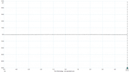
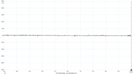
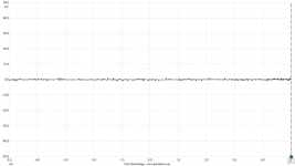
These are my measurements on the LT3045 modules. I used AC coupling to avoid vertical offset. A 50 kHz low pass filter was used to get more accurate measurements in the audible range.
Power on: RMS = 208 uV, 2,9 mV peak to peak
Power off: RMS = 274 uV, 2,6 mv peak to peak
Plugged out: RMS = 61 uV, 653 uV peak to peak
As you can see there is little difference between power on and power off. Therefore I think the regulators are doing a good job. The difference between power off and plugged out is that power off interrupts the +5 V supply to the LT3045, while "plugged out" also turns down the SMPS reading the regulators. This leads me to believe that the noise measured in power on and off is caused by interference from the SMPS rather than something else.
Attachments
I replaced CSET on the LT3045 board with a 22 uF one. Had to use a bigger one than the original because it was the only thing available in that capacitance with the recommended electrolyte. So had the chance to improve my SMD soldering skills. But it worked, see pic. The unit indeed starts up a second or so slower than before. Not sure if I can hear any difference in sound, but it was fun to do...

Last edited:
I replaced CSET on the LT3045 board with a 22 uF .... The unit indeed starts up a second or so slower than before. Not sure if I can hear any difference in sound
Might be a good idea to hook up the AVCC supply(s) very close to the AVCC pins on the dac chip, and ground low side of the supply to the dac ground plane as nearby as possible. Actually, ESS has some recommendations about layout of AVCC supplies, output stages, and a few more things in sort of an application note document on the downloads page of their website. It is a pretty good thing to start getting some ideas from.
You can find it here: ESS Technology :: Downloads
It is the one entitled 'Maximizing DAC Performance for Every Budget.'
EDIT: Also, as it turns out I just purchased one of those dac boards to play around with. It has an ES9028PRO on it, and also the 1.2v voltage regulator. I sat down and sketched up the schematic for it. Think I might change a few things compared to their design though. First thing to go will be the 1.2v regulator, which should be 1.3v for higher performance purposes.
Last edited:
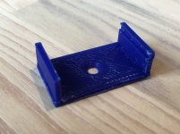
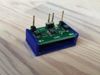
As the little regulator PCBs don't have mounting holes, I designed a bracket to hold one in place. It has a countersunk M3-sized hole for a bolt or screw. A friend of mine was so kind to 3D print them. Attached to this post is the .STL file, for anyone who likes to do the same.
Attachments
Inserted this little TPS7A4701 regulator board between SMPS and RPI. And again the sound improved! The Pi is rated at 1A consumption and the regulator is limited at 1A supply, but this is is enough to power both the Pi and the Hifiberry Digi+ Pro board I have on top of it.
Trying to use this AK4136 board (768K version, PCB v1.3) for upsampling, but haven't gotten it to work yet. This post gives some details, answering Mark's questions in this thread. Pics attached.
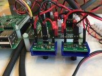
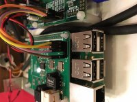
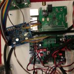
First pic is the previous set-up: RPI running Volumio => Hifiberry Digi+ Pro with header soldered onto I2S output => I2S (GND, Data, BCK, LRCK) to ES9038 board. I stream Airplay to the RPI/Volumio. It works well and sounds good.
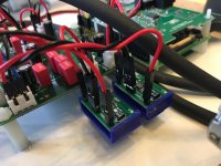
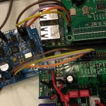
2nd and 3rd pic are of the target situation: RPI running Volumio => Hifiberry Digi+ Pro => I2S connection (GND, Data, BCK, LRCK) to AK4137 board => I2S to ES9038 board
Details:
AK4137 is powered from a TPS7A4701 regulator
I shorted the P/D jumper to force I2S input mode.
Problem (inputting 16/44 as a reference, but other formats have the same prob):
- output modes DSD64/128/256 give sound, but it is worse than when directly connecting the Digi+. Mainly the sound stage is not as good.
- output mode I2S 16 bit 44.1KHz gives no sound at all, or intermittently highly distorted sound.
- all of the other output modes (L-J, R-J, etc.) don't give any sound.
I did some measurements with a scope and the AK4137 board does produce what looks like a correct I2S signal to me. I don't see a difference with the I2S signal coming out of the Digi.
However the signal from the AK4137 just does not seem to be read by the ES9038. Next step I will indeed remove the Digi+ from the set-up and connect AK4137 directly to Pi. Could take me a while though before I get to this.
First pic is the previous set-up: RPI running Volumio => Hifiberry Digi+ Pro with header soldered onto I2S output => I2S (GND, Data, BCK, LRCK) to ES9038 board. I stream Airplay to the RPI/Volumio. It works well and sounds good.
2nd and 3rd pic are of the target situation: RPI running Volumio => Hifiberry Digi+ Pro => I2S connection (GND, Data, BCK, LRCK) to AK4137 board => I2S to ES9038 board
Details:
AK4137 is powered from a TPS7A4701 regulator
I shorted the P/D jumper to force I2S input mode.
Problem (inputting 16/44 as a reference, but other formats have the same prob):
- output modes DSD64/128/256 give sound, but it is worse than when directly connecting the Digi+. Mainly the sound stage is not as good.
- output mode I2S 16 bit 44.1KHz gives no sound at all, or intermittently highly distorted sound.
- all of the other output modes (L-J, R-J, etc.) don't give any sound.
I did some measurements with a scope and the AK4137 board does produce what looks like a correct I2S signal to me. I don't see a difference with the I2S signal coming out of the Digi.
However the signal from the AK4137 just does not seem to be read by the ES9038. Next step I will indeed remove the Digi+ from the set-up and connect AK4137 directly to Pi. Could take me a while though before I get to this.
Attachments
Last edited:
- Status
- This old topic is closed. If you want to reopen this topic, contact a moderator using the "Report Post" button.
- Home
- Source & Line
- Digital Line Level
- Did anyone try one of these ES9028/ES9038 DAC kits?