Hi all,
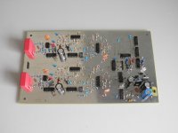
Just for fun I've made a pair of very basic DSD ADCs, that is, sixth-order chaotic sigma-delta modulators that work on the DSD64 or DSD128 sample rate. It tried to construct it out of through-hole components on a double layer board, but some of the capacitors were actually 0805 SMDs because through-hole ceramic class I capacitors in E12 values are hard to get nowadays.
The dynamic range in DSD64 mode is only a mere 80 dB(A) measured with A-weighting and a steep 20 kHz low-pass. That's a consequence of keeping everything as basic as possible: the main feedback DAC is simply a 74AHCT02 gate with a series resistor. I haven't measured the dynamic range in DSD128 mode, but when I just listen to it, the noise appears to drop a few dB when switching to DSD128 mode.
I haven't built the USB interfacing part with the UM245R yet. I use the raw DSD output from U16/P3 (see the attached schematic).
Marcel
Attachments
Last edited:
Just a little update: over the past few weeks, I've tried to further increase the dynamic range using the same logic gates and op-amps. I can increase it to just above 85 dB(A) by taking the feedback to the input of the second integrator from a 74AHCT02 gate, and increasing the passive filtering for the first two stages (C5 and C11, requires a compensating circuit downstream for stability), and reducing C4 (gives better cancellation of low-frequency reference noise). I've tried dozens of other things that didn't help, such as extra shielding and decoupling, using 74AHCT02 gates for third and later stages or using feedforward compensation in the second stage so I could get rid of R12 and R13.
Anyway, to be continued.
Anyway, to be continued.
RustySpoons and Trajan, thanks for the tip and apologies for the late reply. I've had a look at the Potato website, but for this project I wanted to keep everything cheap and easy to solder for a change (my last two hobby projects were expensive and required hand soldering of devices with 0.5 mm pitch), so I decided to use standard products in through-hole packages as much as possible.
The attachments are my latest schematic and an updated PCB layout. The schematic includes all changes that reduce the noise floor (it is around -84 dB(A) to -85 dB(A) now) and three extra changes:
1. Bugfix in the chaos generating part of the original design: it got damped by the base current of the LT1016. An extra positive feedback through a resistor between pins 8 and 3 of the LT1016 is supposed to solve that.
2. R15 reduced to 68 kohm, which increases the resonance frequency of the circuit around U3 from about 10 kHz to about 40 kHz. This makes the in-band noise a few tenths of a dB worse, but much reduces ultrasonic noise.
3. Resistors driving pin 3 of the OPA134 made different for left and right, so both channels have different DC offsets: precaution to avoid idle tones.
Attachments
Very cool Marcel. I really would have liked to build your last project, too bad the group buy never got going.
Once you add the usb interface, this could be a nice little recorder circuit.
BTW, I think surface mount with larger chips would work too, its the fine pitch stuff that tends to scare people.
Randy
Once you add the usb interface, this could be a nice little recorder circuit.
BTW, I think surface mount with larger chips would work too, its the fine pitch stuff that tends to scare people.
Randy
Hi Marcel,
Hmmm... I don't know if one of the aims of this design is that you like to try to make your own DSD ADC (?) ... otherwise I may mention the ADS1204 from TI. Second order modulator with quite good data and likely capable of working up to DSD512 - if there is a way to get it into the computer
Cheers,
Jesper
For me, the challenge was to get a home-made analogue sigma-delta modulator (analogue in, digital out that is) of order greater than two to work. I've designed parts of high-order modulators at work and built complete first- and second-order modulators at home, but never built a complete analogue sigma-delta before.
By the way, I looked at the ADS1204 datasheet and I think it will have a dynamic range of about 70 dB(A) when you use it for DSD64:
Effective number of bits about 12.5 at 64 times oversampling
You lose 1 bit because Scarlet Book DSD doesn't allow you to go beyond 25 % ones/75 % ones
Equivalent SINAD about 68 dB over the Nyquist bandwidth - probably limited by quantization noise, so the dynamic range is the same
A-weighting may add a dB or two
It gets much better at higher oversampling (logical because of the low modulator order).
Last edited:
Hi Marcel ...
Well, I actually was intending to use it for DSD512 (I asked TI about it and they assumed it would work with slightly lower specs) but lately I have been a bit put off by the fact that DSD needs conversion to PCM in order to be edited. So ... but I guess that DSD512 would sound extraordinary if there were a way to get it into the PC - and play it back "raw".
Cheers,
Jesper
By the way, I looked at the ADS1204 datasheet and I think it will have a dynamic range of about 70 dB(A) when you use it for DSD64:
Effective number of bits about 12.5 at 64 times oversampling
You lose 1 bit because Scarlet Book DSD doesn't allow you to go beyond 25 % ones/75 % ones
Equivalent SINAD about 68 dB over the Nyquist bandwidth - probably limited by quantization noise, so the dynamic range is the same
A-weighting may add a dB or two
It gets much better at higher oversampling (logical because of the low modulator order).
Well, I actually was intending to use it for DSD512 (I asked TI about it and they assumed it would work with slightly lower specs) but lately I have been a bit put off by the fact that DSD needs conversion to PCM in order to be edited. So ... but I guess that DSD512 would sound extraordinary if there were a way to get it into the PC - and play it back "raw".
Cheers,
Jesper
Theoretically the quantization noise of a second-order modulator in a given bandwidth should drop with about 15 dB per doubling of the sample rate, so second order should work fine for DSD256 or DSD512 (when the circuitry is fast enough to handle the high sample rate, of course).
I won't comment on the sound, but from a technical point of view single-bit sigma-delta modulates such as DSD have advantages as well as disadvantages compared to PCM. An advantage is that you can generate and demodulate it with relatively simple circuitry without tough matching requirements, disadvantages are that digital signal processing without conversion to some kind of PCM is quite difficult and that you can run into idle tone issues. DSD doesn't require any brick-wall filters, but gives you more ultrasonic noise (DSD512 is much better than DSD64 in that respect). You could argue that that noise doesn't matter because it's ultrasonic, but so is the ringing of the brick-wall anti-aliasing and reconstruction filters used for PCM.
I won't comment on the sound, but from a technical point of view single-bit sigma-delta modulates such as DSD have advantages as well as disadvantages compared to PCM. An advantage is that you can generate and demodulate it with relatively simple circuitry without tough matching requirements, disadvantages are that digital signal processing without conversion to some kind of PCM is quite difficult and that you can run into idle tone issues. DSD doesn't require any brick-wall filters, but gives you more ultrasonic noise (DSD512 is much better than DSD64 in that respect). You could argue that that noise doesn't matter because it's ultrasonic, but so is the ringing of the brick-wall anti-aliasing and reconstruction filters used for PCM.
MarcelvdG,
Unless I'm mistaken I see that your ADC is a 3rd or 4th order design - even with 3rd order you should have plenty of Loop Gain to shape the in-band noise.
Can you post an FFT of the output? - I suspect you have large Even order distortions due to the single ended nature of the feedback DAC arrangement / input stage - personally I'd rearrange the front end / DAC section for balanced operation and things will improve.
Also, you will have higher phase noise then you expect due to noise build up trough the counter / divider circuit - try re-latching the output of the clock diver to the clock input to remove this Phase noise buildup.
Also, the LM317 is very noisy - and has nasty in-band peaking, although you filter the Latch / "DAC" rail these will now have added impedance and still not great LF noise.
Many years ago now, I also tried to build a "simple" 4th order ADC with logic, but could not "simply" resolve idle tones (induced by sweeping a DC input) - the design became so complicated there was no cost saving verses the PCM4202 which has dynamically scaled noise circuit to help "Dither" the idle tones - the PCM4202 is a very good sounding part if its input is driven correctly (but sadly only supports upto 128fs).
Whats the function of U4B - I'm guessing a clever noise source in the loop to help with idle tones?
Also, I'm not used to your Noise shaper structure - but you appear to be pole splitting - I've found that all Poles at DC sounds best (although obviously worst dynamic range).
Unless I'm mistaken I see that your ADC is a 3rd or 4th order design - even with 3rd order you should have plenty of Loop Gain to shape the in-band noise.
Can you post an FFT of the output? - I suspect you have large Even order distortions due to the single ended nature of the feedback DAC arrangement / input stage - personally I'd rearrange the front end / DAC section for balanced operation and things will improve.
Also, you will have higher phase noise then you expect due to noise build up trough the counter / divider circuit - try re-latching the output of the clock diver to the clock input to remove this Phase noise buildup.
Also, the LM317 is very noisy - and has nasty in-band peaking, although you filter the Latch / "DAC" rail these will now have added impedance and still not great LF noise.
Many years ago now, I also tried to build a "simple" 4th order ADC with logic, but could not "simply" resolve idle tones (induced by sweeping a DC input) - the design became so complicated there was no cost saving verses the PCM4202 which has dynamically scaled noise circuit to help "Dither" the idle tones - the PCM4202 is a very good sounding part if its input is driven correctly (but sadly only supports upto 128fs).
Whats the function of U4B - I'm guessing a clever
noise source in the loop to help with idle tones?Also, I'm not used to your Noise shaper structure - but you appear to be pole splitting - I've found that all Poles at DC sounds best (although obviously worst dynamic range).
Last edited:
It's supposed to be sixth order chaotic design. DSD64 sigma-deltas are usually fifth order, but I added an order because the chaos-generating stage doesn't shape very much. It could very well be that two orders less would work just as well.
The reference comes from a 7805, the LM317 is only for supplying some uncritical digital stuff. An LT3042 would definitely be better, but I wanted to keep things simple, cheap and through-hole.
One could replace the clock divider with a synchronous counter, that's even simpler than resynchronizing.
U4B and R95 (in the debugged version) create chaos. They make the loop filter unstable and any stable sigma-delta modulator with unstable loop filter is chaotic: slight differences in initial conditions between two equal modulators will grow exponentially with time until the quantizers make different decisions and the output patterns become very different. Chaos is supposed to reduce idle tones, much like dither.
You can eliminate all filter resonators by removing the local feedbacks: remove R15, R22, R35, R28, and R58, R65, R71, R78 in the other channel.
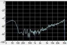
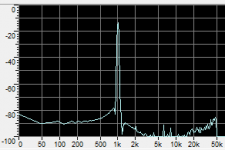
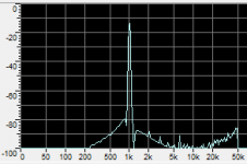
The attached FFT plots are for a cascade consisting of a CD player, the DSD ADC, a DAC and a Fostex FR2-LE recorder - I haven't got any for the DSD ADC on its own. The distortion plots are for a very early version, the noise plot for the final version (with the noise amplified compared to the other plots, obviously).
The reference comes from a 7805, the LM317 is only for supplying some uncritical digital stuff. An LT3042 would definitely be better, but I wanted to keep things simple, cheap and through-hole.
One could replace the clock divider with a synchronous counter, that's even simpler than resynchronizing.
U4B and R95 (in the debugged version) create chaos. They make the loop filter unstable and any stable sigma-delta modulator with unstable loop filter is chaotic: slight differences in initial conditions between two equal modulators will grow exponentially with time until the quantizers make different decisions and the output patterns become very different. Chaos is supposed to reduce idle tones, much like dither.
You can eliminate all filter resonators by removing the local feedbacks: remove R15, R22, R35, R28, and R58, R65, R71, R78 in the other channel.
The attached FFT plots are for a cascade consisting of a CD player, the DSD ADC, a DAC and a Fostex FR2-LE recorder - I haven't got any for the DSD ADC on its own. The distortion plots are for a very early version, the noise plot for the final version (with the noise amplified compared to the other plots, obviously).
Attachments
Hi Marcel,Hi all,
Just for fun I've made a pair of very basic DSD ADCs, that is, sixth-order chaotic sigma-delta modulators that work on the DSD64 or DSD128 sample rate. It tried to construct it out of through-hole components on a double layer board, but some of the capacitors were actually 0805 SMDs because through-hole ceramic class I capacitors in E12 values are hard to get nowadays.
The dynamic range in DSD64 mode is only a mere 80 dB(A) measured with A-weighting and a steep 20 kHz low-pass. That's a consequence of keeping everything as basic as possible: the main feedback DAC is simply a 74AHCT02 gate with a series resistor. I haven't measured the dynamic range in DSD128 mode, but when I just listen to it, the noise appears to drop a few dB when switching to DSD128 mode.
I haven't built the USB interfacing part with the UM245R yet. I use the raw DSD output from U16/P3 (see the attached schematic).
Marcel
I would be interested if you have made an electronic kit for your DSD ADC project? as I am not able to find anything on the market, that will provide me with a digital DSD stream. As I am working on a project here over the last four years, which I am calling my "Advanced Audio Amplifier" that based around my smart amplifier design to input DSD. From inside the processor core I will be converting the DSD to a form of PWM, that can be directly amplified in one of three possible Classes D, I or O. So therefore I need a DSD ADC to connect up my audio signal generator with, If not I have downloaded your files and I will make a start on your circuit and I may make a few updates for my application, then I can do a prototype.
Grant.
No, I haven't made a kit for this circuit (nor for anything else). I also never got the USB interface to work - it can probably be done, but I just lost interest. Besides, I found one very clumsy mistake related to the USB interface: with the way I placed it on the PCB, the USB connector of the module points to some big components, so there is hardly any space to connect the USB cable. Well, if I understand you correctly, you don't need the USB interface anyway.
I hope you downloaded the files attached to post #9, as those are the latest.
If you only need a sort of DSD ADC for very basic functional tests, you could also try this one: https://www.diyaudio.com/community/...delta-for-checking-raw-dsd-interfaces.316898/ Because of its low order, it has only limited noise shaping, but you can drive it to almost 0 % ones and 100 % ones. That can be useful when you want to check how your design responds to overmodulated DSD; DSD is not supposed to go beyond 25 % ones and 75 % ones, but apparently there are DSD files that don't meet that requirement. I never designed a PCB for this ADC, but just built it on a piece of perfboard.
Last edited:
- Home
- Source & Line
- Digital Line Level
- Very basic DSD ADC made with op-amps and logic gates