The output compliance range of the 1387 is a little bit different (1.5V down from the pos supply vs 1.2V down) and its max supply is only 6V. But otherwise you can interchange them from the point of view of the PNP I/V stage.
The difference in sound is rather like what @xx3stksm says in another DAC thread about the difference between an LT and a BB DAC chip. TDA1387 is clearer, more like hires video and TDA1543 is more soft like a photographic film.
The difference in sound is rather like what @xx3stksm says in another DAC thread about the difference between an LT and a BB DAC chip. TDA1387 is clearer, more like hires video and TDA1543 is more soft like a photographic film.
The output compliance range of the 1387 is a little bit different (1.5V down from the pos supply vs 1.2V down) and its max supply is only 6V. But otherwise you can interchange them from the point of view of the PNP I/V stage.
The difference in sound is rather like what @xx3stksm says in another DAC thread about the difference between an LT and a BB DAC chip. TDA1387 is clearer, more like hires video and TDA1543 is more soft like a photographic film.
Great! will place an order for TDA1387 today. Thanks
")
They're super-cheap on Aliexpress nowadays. Last time I checked I couldn't believe how cheap, including free shipping.
One big advantage of 1387 is its low power, so its well suited to portable DAC-AMPs such as the one I'm building now. I just have to figure out how to squeeze it into its case now....
One big advantage of 1387 is its low power, so its well suited to portable DAC-AMPs such as the one I'm building now. I just have to figure out how to squeeze it into its case now....
Attachments
They're super-cheap on Aliexpress nowadays. Last time I checked I couldn't believe how cheap, including free shipping.
One big advantage of 1387 is its low power, so its well suited to portable DAC-AMPs such as the one I'm building now. I just have to figure out how to squeeze it into its case now....
Ha ha nice
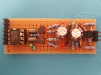
there's some streamlining to do there I guess Talking about squeezing... here's your circuit on a 26x64mm veroboard..
( still need to add all four transistors; added some caps on power supply )
Will check Aliexpress thanks
Attachments
![20180416_105950[1].jpg](/community/data/attachments/613/613266-4f8e0ee14acb99afc4cbb767de7ccec1.jpg)
![20180416_110100[1].jpg](/community/data/attachments/613/613280-4b7c3da67bbc8dd93018fc32927710d3.jpg)
I was thinking 4 initially. The aim of the experiment would be to see if the bass improves still further. If the bass is limited by low frequency noise then paralleling should give a reduction in noise. The result of listening to 4 paralleled modules then would give an indication whether its worth trying more...
Already with my lingDAC the bass to my ears sounds better than any other DAC I've heard, but only with a specially low impedance, low noise supply (well under 1ohm Zout).
P.S.
This (crazy) idea came to me that you could maybe try when you complete your 4x parallel project. Have you ever tried mixing the two (compatible) chips? Wonder what it would sound like using 2xTDA1543 and 2xTDA138 together...
Nope, the idea had never entered my mind prior to your mention of it. Might be worth a try sometime, so many ideas and so little time...
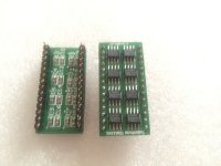
With reference to you project of paralleling TDA1387s, this might save you some time ? :
"HIFI 8 parallel TDA1387 direct substitution TDA1541",
ebay object #132130954983
Attachments
You're using the single transistor I/V on TDA1543? In which case yes you need some bias (by a R on pin7) just as before. But you can get better sound by using your own supplied current source rather than using the one internal to the 1543.
Hello !
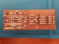
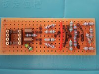
One side of my previous circuit was popping all the time so I just decided to start again from scratch with fresh components...
Now it's neater
If you have a minute or two...could you kindly show me what you meant by "using your own supplied current source" ?
Thanks
Attachments
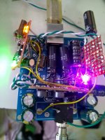
Ps here's the player if you want a closer look.
Sorry to hijack this thread but I bought one of these from AliExpress. Can't seem to get it to work. What sort of i2S does it O/P? Left Justified? Right Justified?
No Intructions supplied and no Remote like in the picture here. Ah well, it was pretty cheap !!
P.
Sorry to hijack this thread but I bought one of these from AliExpress. Can't seem to get it to work. What sort of i2S does it O/P? Left Justified? Right Justified?
No Intructions supplied and no Remote like in the picture here. Ah well, it was pretty cheap !!
P.
Hi ! the player's I2S ouput can be fed directly to a TDA1543 dac chip, so for exact specifics about the format check the TDA1543's datasheet.
The dac is also a good starting point for any diy
If you have a minute or two...could you kindly show me what you meant by "using your own supplied current source" ?
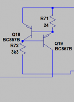
This is what a current source looks like - the top line is the +ve supply. Then you need to connect the bottom end of R72 to 0V and the collector of Q19 to the DAC's output (pin6 or 8). The resistor values shown are wrong, you'll want R71 to be 240 ohms and R72 as 33k.
Attachments
Hi ! the player's I2S ouput can be fed directly to a TDA1543 dac chip, so for exact specifics about the format check the TDA1543's datasheet.
The dac is also a good starting point for any diy
Thanks for that.
I'll give it another go. I was just getting a lot of noise. Maybe my leads were too long.
It also didn't like some 88.2kHz content. It made the whole display flicker !
P.
Thanks for that.
I'll give it another go. I was just getting a lot of noise. Maybe my leads were too long.
It also didn't like some 88.2kHz content. It made the whole display flicker !
P.
Yes...and (in case you haven't) please connect the player's and dac's grounds (which is how this whole thread started).
In my case that was causing the noise.
This is what a current source looks like - the top line is the +ve supply. Then you need to connect the bottom end of R72 to 0V and the collector of Q19 to the DAC's output (pin6 or 8). The resistor values shown are wrong, you'll want R71 to be 240 ohms and R72 as 33k.
Thank you ! Really appreciated.
Yes...and (in case you haven't) please connect the player's and dac's grounds (which is how this whole thread started).
In my case that was causing the noise.
Yup, that's exactly what I hadn't done. Feel like a right idiot !!
Thanks for your help.
P.
P.S. Still not playing 88.2kHz but will start another thread for that. Sorry for hijacking this thread so far !!
This is what a current source looks like - the top line is the +ve supply. Then you need to connect the bottom end of R72 to 0V and the collector of Q19 to the DAC's output (pin6 or 8). The resistor values shown are wrong, you'll want R71 to be 240 ohms and R72 as 33k.
Hello! So the complete circuit should look like this... ?
Attachments
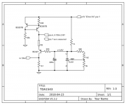
Something's wrong - the external current source isn't for TDA1387 (its internal one can't be disabled) rather for TDA1543. Other than that the circuit looks like it should - the 240R resistor though I'm not certain is the right value, I need to look into that. Its value would depend on the supply voltage to the 1543.
Something's wrong - the external current source isn't for TDA1387 (its internal one can't be disabled) rather for TDA1543. Other than that the circuit looks like it should - the 240R resistor though I'm not certain is the right value, I need to look into that. Its value would depend on the supply voltage to the 1543.
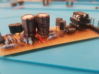
After some serious debugging (a very sneaky short causing trouble), finally have two working versions of the (simplified/first) circuit, that I am satisfied with.
4x1.2V for player and 5x1.2V on dac.
Had the impression that different brands of the BC327 give different sound.
Overall very happy with sound. Will do more testing.
Attachments
![20180429_110918[1].jpg](/community/data/attachments/633/633731-9465e270009503b46e9d0d25cb9ac75f.jpg)
- Status
- This old topic is closed. If you want to reopen this topic, contact a moderator using the "Report Post" button.
- Home
- Source & Line
- Digital Line Level
- A story of mysterious interaction between a diy tda1543 dac setup and the human body.