au-trouvaille,
The posted schematic seems readable to me. If it seems too small, it may be that it is not being displayed at full resolution. If you open it by clicking on it with a mouse, then hover over the image with the mouse, a sort of white X will appear in the lower left corner. Click on the X to see the image at full resolution. Or, it can be downloaded by opening it, then right clicking to 'save image.' The file will download it full resolution. Also, I am not aware of any other version of the schematic.
The posted schematic seems readable to me. If it seems too small, it may be that it is not being displayed at full resolution. If you open it by clicking on it with a mouse, then hover over the image with the mouse, a sort of white X will appear in the lower left corner. Click on the X to see the image at full resolution. Or, it can be downloaded by opening it, then right clicking to 'save image.' The file will download it full resolution. Also, I am not aware of any other version of the schematic.
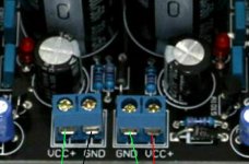
A pic of the voltage regulator board I recommend is attached below.
Occurred to me that I should have edited the regulator pic to show the red (+15v), black (-15v), and green (dac ground) wires.
Also, please remember the transformer must have separate windings to power each of the +15v and -15v regulators. A center-tapped winding will not work for this.
Attachments
Last edited:
Thanks for clearing that up. Why is there an input labelled GND, 5V? is it there only for people who will remove one regulator from the board?
Using a power supply with higher current capacity than necessary can improve sound quality. Is there a factor beyond which using bigger power supplies no longer helps, like 10x? What is the current draw of the board when using the dual 15V supplies?
how much of that current would be elimnated if I bypassed the 5V regulator?
is it correct to say that bypassng the 5V regultor would leave the opamps as the only components using the 15V supplies?
if so, how much current do they use?
how about the components in-between the 5V and 3.3V regs?
and lastly, how much current do all the components after the 3.3v reg. use together in total?
I am going to remove the 5V regulator later on as I already have an lt3042 5V regulator and a good trafo for it.
Is the I/V output stage another type of preamp?
The other question was about using some additional regulators such as LT3042, that is only for if you want to remove the 5v and 3.3v regulators from the dac board and use your own 3.3v regulators instead. The existing 5v regulator uses the +15v for input and drops it down to +5v, then another smaller regulator drops the +5v down to +3.3v. That +3.3v is used to power the dac chip, the clock, the MCU, the optical receiver, and the SPDIF buffer inverter (everything that needs +3.3v power).
If the +5v and the +3.3 regulators are removed from the board, then we could talk about how to replace them with better regulators. In that case the +15v and -15v power would only be used for the opamps. However, best to keep it simple if you are having trouble understanding.
The +5v and +3.3v regulators I am talking about are labeled U1 and U2 on the schematic attached below.
Last edited:
Quick answer on one question, the other questions may have to wait awhile longer. At the I2S input connector there is a terminal marked ground and one marked 5v. The ground is for all of the I2S inputs. The 5v terminal is an power output, not an input. It can be seen on the schematic as an output. It might have been put there to eventually power a optional USB board or something like that, don't know since it never did get used.
Using a power supply with higher current capacity than necessary can improve sound quality. Is there a factor beyond which using bigger power supplies no longer helps, like 10x?
There is not a particular rule of thumb I am aware of for that. Some regulators seem to work best with a certain voltage drop across them. Some seem to work better when operating at a particular output current.
Some people say its good for analog audio circuit sound quality if the frequency/phase/impedance output characteristics of + and - rail power supplies are matched over the audio band. If they are right, that may be one reason why using a two positive regulators such as LT1083 to supply both of the +/- rails tends to produce a good SQ result.
What is the current draw of the board when using the dual 15V supplies?
IIRC correctly when only using +-15v supplies, the + rail may be around 145mA and the negative rail much less, guessing maybe around 20mA. Could be more than that but probably not too much more. I know it could run from 'Silent Switcher' power supply which only spec'ed for 150mA. Also, IIRC the exact numbers are posted in the thread somewhere; a search might find them.
Is the I/V output stage another type of preamp?
I wouldn't call it a preamp exactly. Its a current to voltage converter that also does low pass filtering, converts balanced outputs to single ended, and that removes DC offset coming from the dac chip outputs. There is a lot going on in all at once with 3 opamps. Please see the recommended I/V and AVCC schematics attached to post #3003. In addition, I can provide a link to instructions for a project to hand construct an output stage using through-hole components if there is interest.
EDIT: I think I once posted a layout for a possible SMD I/V stage built on Surfboard adapters (maybe I could find that too if there is interest): SURFBOARDS FOR I.C.s Model 9081 Surface Mount Breadboard
Last edited:
For anyone interested, there has been some recent activity in another thread: Luxman uses ROHM Semiconductor MUS-IC BD34301EKV dac
I kill mcu my ak4137 5 560,52 руб. 8%СКИДКА | AK4137 флагманский высококлассный DAC SRC Audio 384K 32Bit DSD256 DSD PCM Конвертация
AK4137 Flagship High end DAC SRC Audio 384K 32Bit DSD256 DSD PCM Conversion|Switch Caps| - AliExpress ((( i have a working mcu from es9038q2m. And can replace this mcu. But not have a program for this mcu for working with this ak4137..and don't know how replace program. can anybody help me?
AK4137 Flagship High end DAC SRC Audio 384K 32Bit DSD256 DSD PCM Conversion|Switch Caps| - AliExpress ((( i have a working mcu from es9038q2m. And can replace this mcu. But not have a program for this mcu for working with this ak4137..and don't know how replace program. can anybody help me?
Okay. I can probably help with both ES9038Q2M and AK4137. The AK4137 is actually a little bit more complicated because the original MCU directly controls some pins instead of using I2C for everything. There is also an I2C controlled latch chip that programs some of the AK4137 pins.
One thing at a time, do you want to start with the 9038Q2M or with AK4137. I would suggest the dac will be easier.
Regarding the PCA9306 you have, is it on a board or a loose chip? If a chip, which version package do you have?
EDIT: Regarding an example I2C program to get you started, I have a test version file that can read and write to I2C registers. It is at: Dropbox - Latest.zip - Simplify your life ...it also need an Arduino library file that can be downloaded from: GitHub - felias-fogg/SoftI2CMaster: Software I2C Arduino library ...Also good to read the info on the download page to understand how I2C register reading and writing works.
EDIT 2: Can you make a small PCB if it will make things easier? If not, there are other ways.
Last edited:
If you have one of the green boards with display, seems to me that putting a jumper across two of the input selection header stopped the mcu for some people. Don't remember which jumper it was at the moment though. This is the pin header used for SPDIF/TOSLINK/I2S input selection if there no display and remote control. If you can halt the MCU that way with your board, that makes it easier.
There is a post with links to I2C mod info, and a couple of posts down from that are the post numbers for people using non-standard forum page display lengths. ES9038Q2M Board ...Suggest reading through the linked posts to get any idea about hooking into the I2C lines. If any questions, please ask.
The only thing using an isolator chip changes is that it goes between the I2C lines from the dac board, and the I2C lines going to Arduino. The dac board +3.3v and GND powers the dac side of the isolator, and the Arduino +5v and GND powers the Arduino side. Don't tie the two grounds to each other or they won't be isolated from each other.
EDIT: Also just found this note:
Post #2873 - I2C trace cut and patch mod for blue boards (green boards use J1, J2 installed instead)
https://www.diyaudio.com/forums/digital-line-level/314935-es9038q2m-board-288.html#post5565005
(note: green boards only need I2C leads attached, but no pin lift or trace cuts)
Apparently, it was J1, J2 both installed that halted the green board MCU, but depending on firmware version. If that trick works with your board, then hooking up to I2C is much more simple.
Last edited:
I have a blue version. 774,46 руб. 10%СКИДКА | ES9038Q2M ES9038 Q2M I2S DSD оптический коаксиальный IIS/DSD DOP 384 кГц входной декодер DAC для наушников выходной аудио усилитель плата
ES9038Q2M ES9038 Q2M I2S DSD Optical Coaxial IIS/DSD DOP 384KHz Input Decoder DAC Headphone Output Audio amplifier Board|Amplifier| - AliExpress
ES9038Q2M ES9038 Q2M I2S DSD Optical Coaxial IIS/DSD DOP 384KHz Input Decoder DAC Headphone Output Audio amplifier Board|Amplifier| - AliExpress
I think i want save mcu, I use remote control and have display.
I not remembered how this work to including Pca9306
Just keep in mind that you will not be able to use the two mcus concurrently - so you'll either have remote control & display (using the on-board mcu) or use your outboard mcu.
- Home
- Source & Line
- Digital Line Level
- ES9038Q2M Board