Yes. my inner cynic wondered if it might just be ESS wanting to price gouge everyone. I notice the 9028PRO is still in stock at Mouser. I already have 9018PRO dacs and consider nearly $90AUD already too much for the 9028; as its not a top of the line product anymore. i'm uninterested in pursuing a 9028 design; I guess i'll just find other things to work on for the next 4 months.
Anyway. Sorry guys. thats the last i'll mention of it in here. I'm just very frustrated and venting. I'm sick of redesigning this DAC, due to supply issues.
Anyway. Sorry guys. thats the last i'll mention of it in here. I'm just very frustrated and venting. I'm sick of redesigning this DAC, due to supply issues.
Last edited:
^^^
Was thinking myself about using (for my little instrumentation project) the ES9028PRO, for the time being, at the first glance it appears the ES9038PRO is a pin to pin replacement, only with better performance (in fact I believe it's the same silicon, sorted by performance metrics). But then ES9028 is expensive enough for my DIY budget, not sure if it's worth going this route.
Was thinking myself about using (for my little instrumentation project) the ES9028PRO, for the time being, at the first glance it appears the ES9038PRO is a pin to pin replacement, only with better performance (in fact I believe it's the same silicon, sorted by performance metrics). But then ES9028 is expensive enough for my DIY budget, not sure if it's worth going this route.
You keep doing your thing, please slow down and look carefully at what you are doing.
There's nothing to compare the cable short results, other than maybe with your previous result with the DAC "idle" or powered down? Please check the input short result, as follows: your cable has two ends at the DAC board: ground and "hot". The ground end goes to the DAC board ground; keep it there, then connect the "hot" end to the same ground. Do not touch anything between measurements. Now, measure with the DAC powered down, "idle", then with the DAC board @1KHz full scale. Post the results.
You mean like images 2, 3 and 4 from post 6753 but with the cable hot shorted to the ground that the cable ground is already soldered to?
Last edited:
Yes, like in all 1-6 in that post. Or anything else that could allow a direct comparison between shorted measurement and the real measurement. Better do a new set of both,
a) Decide for something to measure, say the AVDD noise
b) Consecutively (measure the AVDD noise, then measure the short noise). Don't touch anything else in between.
c) Repeat b) for the next DAC state - powered down, idle, 1KHz full scale
d) Post the results
a) Decide for something to measure, say the AVDD noise
b) Consecutively (measure the AVDD noise, then measure the short noise). Don't touch anything else in between.
c) Repeat b) for the next DAC state - powered down, idle, 1KHz full scale
d) Post the results
Last edited:
You too, please. Thank you.
since when moderation is off-topic?
Ironically; I may just knock up some 2 channel versions to test out power supply, clocking and the ADC, with 9038Q2M. I was planning on trying it for an integrated instrumentation project myself anyway. If I do, i'll return with any tips I have here for you guys.
FOMO may require me to grab some 9028 if they still have any in stock on payday. Looking at the datasheet, power supply requirements for everything is significantly lower. AVCC_L/R are only 47ma vs ~100 for 9038, so if its the same silicon, it's the same silicone twice in parallel.
FOMO may require me to grab some 9028 if they still have any in stock on payday. Looking at the datasheet, power supply requirements for everything is significantly lower. AVCC_L/R are only 47ma vs ~100 for 9038, so if its the same silicon, it's the same silicone twice in parallel.
Last edited:
since when moderation is off-topic?
Forum Rules said:Threads or posts about site moderation are not allowed and will be closed and/or deleted.
Ok. That took awhile and fortunately I was able to do it without damaging anything.
I am pretty confident that the 60Hz would be lower if I had designed the boards and used a tiny connector (maybe IPX) for test points. Anything sticking up is another antenna when trying to do this.
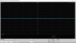
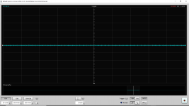
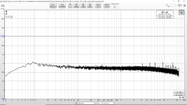
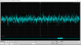
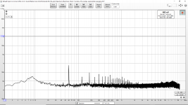
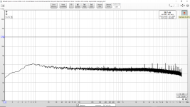
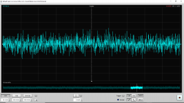
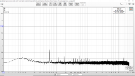
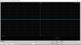
This is the AMS1117 input (output of the LM7805). All scope images are 50uV per division. Shorted means probe cable ground and hot both grounded to AMS1117 ground. In order they are:
DAC powered on, output section powered on. DAC idle:
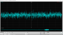
DAC powered on, output section powered on. 1kHz fullscale:
The rest in the next post due to the number of attachments.
I am pretty confident that the 60Hz would be lower if I had designed the boards and used a tiny connector (maybe IPX) for test points. Anything sticking up is another antenna when trying to do this.
This is the AMS1117 input (output of the LM7805). All scope images are 50uV per division. Shorted means probe cable ground and hot both grounded to AMS1117 ground. In order they are:
DAC powered on, output section powered on. DAC idle:
- Shorted waveform and spectrum.
- Waveform and spectrum
DAC powered on, output section powered on. 1kHz fullscale:
- Shorted waveform and spectrum.
- Waveform and spectrum
The rest in the next post due to the number of attachments.
Attachments
-
 SHORTED Scope Input To AMS1117 DAC Powered Output On.png49.5 KB · Views: 153
 -
 Input To AMS1117 DAC Powered Output On 1kHz Full Scale.png75.2 KB · Views: 60
 -
 Scope Input To AMS1117 DAC Powered Output On 1kHz Full Scale.png136.2 KB · Views: 73
 -
 SHORTED Input To AMS1117 DAC Powered Output On 1kHz Full Scale.png76.4 KB · Views: 63
 -
 SHORTED Scope Input To AMS1117 DAC Powered Output On 1kHz Full Scale.png43.5 KB · Views: 158
 -
 Input To AMS1117 DAC Powered Output On.png77 KB · Views: 145
 -
 Scope Input To AMS1117 DAC Powered Output On.png136.3 KB · Views: 158
 -
 SHORTED Input To AMS1117 DAC Powered Output On.png77.7 KB · Views: 156
Last edited:
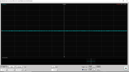
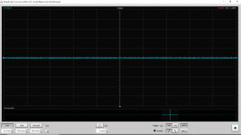
This is the AMS1117 input (output of the LM7805). All scope images are 50uV per division. Shorted means probe cable ground and hot both grounded to AMS1117 ground. In order they are:
All DAC power off:
DAC powered on, output section powered off:
Further measurements at my standard fee. And after someone posts similar measurements from a very good or great ES9038Q2M implementation...
All DAC power off:
- Shorted waveform and spectrum.
- Waveform and spectrum
DAC powered on, output section powered off:
- Shorted waveform and spectrum.
- Waveform and spectrum
Further measurements at my standard fee. And after someone posts similar measurements from a very good or great ES9038Q2M implementation...
Attachments
-
 Input To AMS1117 DAC Powered Output Off.png127.3 KB · Views: 57
 -
 Scope Input To AMS1117 DAC Powered Output Off.png135.9 KB · Views: 60
 -
 SHORTED Input To AMS1117 DAC Powered Output Off.png74.1 KB · Views: 56
 -
 SHORTED Scope Input To AMS1117 DAC Powered Output Off.png46.6 KB · Views: 65
 -
 Input To AMS1117 OFF.png75 KB · Views: 61
 -
 Scope Input To AMS1117 OFF.png46.3 KB · Views: 71
 -
 SHORTED Input To AMS1117 OFF.png76.9 KB · Views: 62
 -
 SHORTED Scope Input To AMS1117 OFF.png44.5 KB · Views: 69
Last edited:
Originally Posted by Forum Rules
Threads or posts about site moderation are not allowed and will be closed and/or deleted.
anyone sane sees it means CHALLENGING moderation, not endorsing

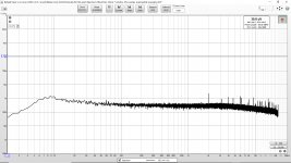
You probably picked the less relevant place to measure the power supply noise, the output of the 7805, the AVDD DAC pin would be much more so. Nevertheless, the results are showing that while you have some ground loop noise (if I’m reading correctly, 3nV/rtHz is over your alleged LNA noise) and then the 7805 output noise is about 200nV/rtHz, which is of the order of magnitude I would expect (50uV/sqrt(100khz)=160nV/rtHz).
This value is very high, I have no idea what would be at the AMS1117 output, much less at the AVDD pin(s) since there are some filtering and decoupling on the way. Measure if you want to, you are not doing me any favour. You can for now skip the short measurement, since you know your measurements limit, the LNA noise. For your reference, the VREF noise (LTC6655 plus LT3045) for my instrumentation ADC project is slightly over 5nV/rtHz and the AVDD noise (LT3045) is around 7nV/rtHz. These are about 50 times less than what you currently get at the 7805 output.
This value is very high, I have no idea what would be at the AMS1117 output, much less at the AVDD pin(s) since there are some filtering and decoupling on the way. Measure if you want to, you are not doing me any favour
. You can for now skip the short measurement, since you know your measurements limit, the LNA noise. For your reference, the VREF noise (LTC6655 plus LT3045) for my instrumentation ADC project is slightly over 5nV/rtHz and the AVDD noise (LT3045) is around 7nV/rtHz. These are about 50 times less than what you currently get at the 7805 output.
Last edited:
anyone sane sees it means CHALLENGING moderation, not endorsing
Sir, can I help you in any way, shape or form? Do you have to add anything relevant to the current discussion, or you are only looking to pick up a fight?
If you want to design audio stuff by ear, be my guest to do so. But please do not expect to have a smooth ride, and expect challenges when you post unsubstantiated claims.
You probably picked the less relevant place to measure the power supply noise, the output of the 7805, the AVDD DAC pin would be much more so. Nevertheless, the results are showing that while you have some ground loop noise (if I’m reading correctly, 3nV/rtHz is over your alleged LNA noise) and then the 7805 output noise is about 200nV/rtHz, which is of the order of magnitude I would expect (50uV/sqrt(100khz)=160nV/rtHz).
This value is very high, I have no idea what would be at the AMS1117 output, much less at the AVDD pin(s) since there are some filtering and decoupling on the way. Measure if you want to, you are not doing me any favour
AVCC_R is in post 6754. VCCA is in post 6756. Not surprisingly both are lower. I measured the 7805 output because I plan to replace it and I want before and after measurements. I don't plan to stick with the noisy regulators. But I do like to measure before and after I make changes.
Any chance you can post some measurements from the LTC6655 plus LT3045? (At the DAC pin? Not a reference or regulator alone.)
Earlier noise measurements during the debugging and verification of the LNA was in post 6493 and post 6498. [Some, not all.] Post 6498 has measurements with a 60 dB LNA soldered directly to the input of the LNA (100Ohm and 100kOhm) which makes a pretty nice low noise way to test the LNA.
Typically I always made measurements with the power off (to look at LNA noise) but I can switch to measurements with the LNA shorted first, if that is better.
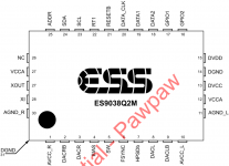
FYI: I am using the pin names that ESS uses in their datasheet. (Attached.)
Attachments
Last edited:
anyone sane sees it means CHALLENGING moderation, not endorsing
I expect it also applies to people pretending to be moderators ...
Sir, can I help you in any way, shape or form? Do you have to add anything relevant to the current discussion, or you are only looking to pick up a fight?
If you want to design audio stuff by ear, be my guest to do so. But please do not expect to have a smooth ride, and expect challenges when you post unsubstantiated claims.
Not sure who wants to pick up a «fight», like you say....
So Einstein's quote is unsubstantiated?
MANY people at one point discriminate by ear, because ultimately huamns listen to music, usually. Not just me. It's not just a question of skill but limitation of ressources. Also, many people noticed your arrogance, be sure of that.
And since you ask me what do i want...like i said MANY way too much times, i ask to stay on topic, and to respect people when they think something SOUNDS better than another thing. You think dac designers never listen to their stuff before final stage of market release? give us a break....
Any chance you can post some measurements from the LTC6655 plus LT3045? (At the DAC pin? Not a reference or regulator alone.)
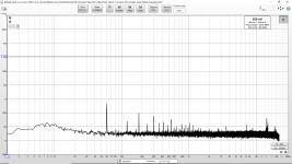
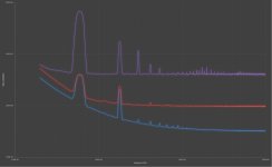
Attached, 20Hz-10KHz. Bottom (blue) is the LNA input shorted, mid (red) is a 50ohm resistor, top (purple) is the 2.5V VREF noise, ADC running with a 1KHz FS input. The LNA and the ADC are not shielded in this case, hence the rather large mains harmonics. LNA gain is 60dB.
Attachments
This is the AMS1117 input (output of the LM7805).
Even though the noise on the supply lines is quite high you could try switching to a current output stage since that is something you need to do anyhow. Sort of picking the low hanging fruits first. Another thing is that the noise of your current setup (7805+AMS1117) is probably low enough for the digital circuitry (DVCC) so you can first focus on AVCC and maybe VCCA. Switching to TPS7A20 may not be needed for DVCC.
Attached, 20Hz-10KHz. Bottom (blue) is the LNA input shorted, mid (red) is a 50ohm resistor, top (purple) is the 2.5V VREF noise, ADC running with a 1KHz FS input. The LNA and the ADC are not shielded in this case, hence the rather large mains harmonics. LNA gain is 60dB.
Thank you for the data. When I start putting together candidates for the Vref I will trying measuring them along with small resistors such as 0, 50, 100Ohm. I have 3x parallel 2N4403 right now but I might be able to get some 2SB737 but that will take time. If that doesn't work out I can get ZTX951 in the order with additional good op-amps, ref and regulators.
There are actually a couple variants of the LNA setup and when I have to use SPDIF and when I have to measure something physically large that is actually the worst setup. When I measure something physically compact and also when I don't need SPDIF then a couple of interfering factors are reduced. In addition the better setup has much better LF response. The LF response is poor for the setup with SPDIF.
Even though the noise on the supply lines is quite high you could try switching to a current output stage since that is something you need to do anyhow. Sort of picking the low hanging fruits first. Another thing is that the noise of your current setup (7805+AMS1117) is probably low enough for the digital circuitry (DVCC) so you can first focus on AVCC and maybe VCCA. Switching to TPS7A20 may not be needed for DVCC.
I do plan to do both. (Switch to a current output stage and improve the regulators and reference.)
I will need to build prototypes and do some testing but one of my ideas can provide many outputs of Vref. Basically I will pre-regulate a supply (perhaps 12V) for the reference and multiple op-amp filters like the recommended VCCA_R/L supplies. But instead of one op-amp filter I am thinking of three dual op-amps for six filtered outputs. One of the dual op-amps will be a LM4562 dual for two VCCA_R/L outputs. The other two dual op-amps will likely just be NJM5532DD to provide four other low noise low current supplies. Although one could be NJM4556ADD for higher current.
Thus when I build this (if it measures well) I will have six very low noise low current supplies. Enough for a 54mW DAC, Atmel ATTINY, SPDIF.
If it works I can remove the LM7805, AMS1117-3.3 and later work on the current output.
The current output modifications might be last since my recent ES9038Q2M measurements show a 2nd harmonic that is exactly equal to the 2nd harmonic of my ADC when I do the loopback test. So I need time to improve the ADC. After improving the ADC then I can measure a better output and also that is likely the time I will try J-Test.
- Home
- Source & Line
- Digital Line Level
- ES9038Q2M Board