Based on the second picture in post #6485 the higher 1/f noise comes from the LNA. You should see that even with Realtek.
I have attached screen shots of the response overlays to make it easier to see.
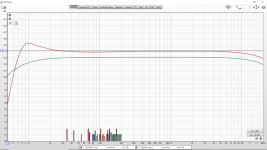
The first shows "Loopbacks of SB0490 Alone and SB0490 With Attenuator And LNA".
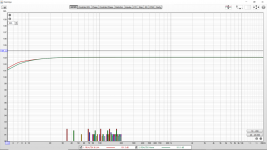
The second shows "Loopbacks of REALTEK Alone and REALTEK With Attenuator And LNA".
The third shows "Response of All Four Combinations of Audio Interface and LNA".
I believe the combination of REALTEK with the LNA is ok.
Attachments
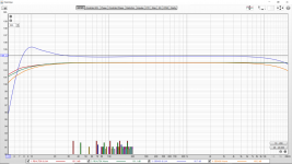
Strange that the low-frequency hump is only visible in SB0490+LNA. Maybe syn08 can chime in and explain this "perfectly normal" behaviour.
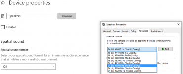
I noticed from the earlier screen shots that your Realtek is running 48k/16bits. Maybe you should check if 24bits is possible with Realtek.
I noticed from the earlier screen shots that your Realtek is running 48k/16bits. Maybe you should check if 24bits is possible with Realtek.
bohrok2610; said:Strange that the low-frequency hump is only visible in SB0490+LNA.
I would be interested in hearing possible explanations. Right now I plan to proceed with the REALTEK + LNA combination. In the future a better interface would be desirable.
bohrok2610; said:I noticed from the earlier screen shots that your Realtek is running 48k/16bits. Maybe you should check if 24bits is possible with Realtek.
I will look into that.
You should read this -> https://www.diyaudio.com/forums/digital-line-level/331363-ak4499eq-dac-71.html#post6449262Rather than just dismissing out of hand what people claim to hear as being misguided, irrelevant or even deliberately misleading, wouldn't it be better to examine where and why our measurements do not explain what people claim to be hearing? For me this is just a hobby and I am tired of the aggression and arrogance of people with closed minds.
I might have particularly wonky hearing and my findings might be irrelevant to others as a result but I don't think we are in a position to prove that yet and I would like to reach that point, one way or another. Every time I hear an improvement which I can't explain I find it extremely annoying and frustrating. Some of these unexplained improvements are really quite obvious and really don't require DBT. IMHO our current crop of measurements doesn't comprehensively explain everything we hear or get the emphasis and balance right.....yet. If they did then we wouldn't be having this discussion.
John
PS If there is a DIYaudio thread already in existence where this "explaining of subjective findings" is already being discussed then perhaps some kind soul could guide me towards it. I don't want to derail this very valuable thread any longer.
I noticed from the earlier screen shots that your Realtek is running 48k/16bits. Maybe you should check if 24bits is possible with Realtek.
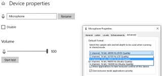
I checked and it is not. Output is supported at 24 bits but not input. (See attached.)
Also the loopback (REALTEK alone) results become rubbish if I select 192kHz. I assume the DAC can handle 192kHz (and 24 bits). But the ADC seems to be less capable and can handle 48kHz at 16 bits.
The ADC properties list 192kHz at 16 bits but the loopback is rubbish with very high distortion even from 10kHz to 20kHz where the 48kHz loopback is good.
Attachments
I think we have found it.
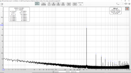
In this experiment the first picture is with the external USB audio interface "Sound Blaster Live! 24 Bit SB0490". Note the 60Hz & 180Hz.
The second picture is with the internal REALTEK sound interface that is built into the laptop. The 60Hz & 180Hz is gone. (However it is traded for some high frequency spurs that we at least now know are nothing to do with the LNA.)
Note that the levels shown are at the output of the LNA with 60 dB gain. So input levels are 1000 times smaller than shown.
[The other experiment where I placed the SB0490 inside the shielding changed nothing.]
The 1KHz harmonics are certainly coming from the USB, 1KHz is the USB micro frame frequency.
Strange that the low-frequency hump is only visible in SB0490+LNA. Maybe syn08 can chime in and explain this "perfectly normal" behaviour.
I noticed from the earlier screen shots that your Realtek is running 48k/16bits. Maybe you should check if 24bits is possible with Realtek.
Elementary my dear Watson: likely the SB490 has (like many sound cards and sound interfaces) a limited LF response, hence the apparent drop in noise. To compensate, some manufacturer are using a bootstrap technique to extend the LF response. It is easy to overdo it and get the hump.
Or simple the sound device has the equalizer on, with a LF boost.
Everything is off (all enhancements are disabled).
Rather than just dismissing out of hand what people claim to hear as being misguided, irrelevant or even deliberately misleading, wouldn't it be better to examine where and why our measurements do not explain what people claim to be hearing?
No, nobody sane will attempt to investigate anything, before the claimant proves he can really hear it and it is not simply an psycho-acoustic illusion. Life is simply too short to attempt to investigate and explain any listening report, even if this means missing a 0.01% chance to get something useful out of it. This falls under "an extraordinary claim require extraordinary proof" category.
So I would like your opinions. Are the enclosed results indicative of a suitable measurement level for looking at the supplies on the ES9038Q2M and AK4396 boards? I think these noise levels are far below that of the regulators that are installed on these boards? (The noise levels, not the 1kHz test sine wave.)
Would the measurements be considered meaningful and worthwhile? In case it is not obvious the 1kHz is a test signal that is being put through a 60 dB attenuator to test the 60 dB gain LNA. The 1kHz generator is of course producing the normal assortment of harmonics.
Would the measurements be considered meaningful and worthwhile? In case it is not obvious the 1kHz is a test signal that is being put through a 60 dB attenuator to test the 60 dB gain LNA. The 1kHz generator is of course producing the normal assortment of harmonics.
Attachments
Last edited:
Sorry Sherlock, you got that wrong. In post #6501 SB0490 has increased LF response when paired with the LNA.
Dear Watson, I can't tell more without seeing the schematics. That's "normal", I would think.
...Would the measurements be considered meaningful and worthwhile?
Might depend on who is doing the considering.
Also, might depend on what you find. Say, if you find a problem and fix it, then maybe it will have been worthwhile for you
")
Did a test with DPLL settings this weekend with some friends.
I was surprised that the diffrent was so big between settings 1(lowest i could get a lock) and 15.
15 sounded a little ”dull”..But between default 5 and settings 1 the diffrent was not that big but we all could here the improvment.
BR //Daniel
I was surprised that the diffrent was so big between settings 1(lowest i could get a lock) and 15.
15 sounded a little ”dull”..But between default 5 and settings 1 the diffrent was not that big but we all could here the improvment.
BR //Daniel
Hi Daniel,
Thank you for sharing your listening impressions.
Since the changes you made seemed small to you, I wonder if other issues in the dac or, maybe, say, in your power amp, etc., might be masking some effects of the change. However, can't say I know that's the case, just wondering is all.
Regarding going below at DPLL_Bandwidth setting of 1, a setting of 0 actually disables the DPLL. Therefore, it can only work in fully synchronous mode.
Last edited:
Might depend on who is doing the considering.
Also, might depend on what you find. Say, if you find a problem and fix it, then maybe it will have been worthwhile for you
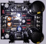
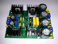
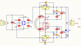
I will look into the lower noise LT and Ti regulators soon. However to start out the attached pictures and schematics show the four supplies that I have already that I use for preamplifier, LNA and DAC usage.
In preparation for my new ES9038Q2M (the recommended one) could you please suggest which of the four power supplies would be the best starting point for powering the board recommended ES9038Q2M board?
First picture and schematic: LM317 Parallel Regulated Shunt Power Supply
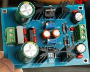
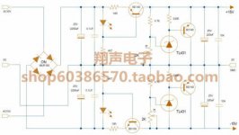
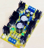
Second picture and schematic: Class A Parallel Regulated Power Supply
Third picture and schematic: LM317 LM337 LF353 Active Servo
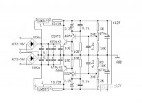
Fourth picture and schematic:LM317 LM337 Adjustable Power Supply
I assume either the first or the second would be the best of the supplies that I already have. However I am curious about the suitability of the third ("LF353 Active Servo").
I also wonder if the PSRR of the operational amplifier, the LM7805 and the AMS1117-3.3 added to that of the fourth supply (regular LM317/LM337) is sufficient? (Based upon when I put the LM7812/LM7912 on the AK4396 board after the LM317/LM337 as a preregulator and I could no longer see 60Hz or harmonics from the AK4396 output.) The AVCC seems to be a separate/different discussion due to the zero PSRR.
Attachments
-
 LM317 LM337 Adjustable Filtering Power Supply.jpg101.5 KB · Views: 122
 -
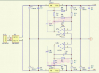 LM317 LM337 LF353 Active Servo Schematic.png531.5 KB · Views: 127
 -
 LM317 LM337 LF353 Active Servo.jpg622.1 KB · Views: 126
 -
 Class A Parallel Regulated Power Supply Schematic.jpg24.5 KB · Views: 279
 -
 Class A Parallel Regulated Power Supply.png365.1 KB · Views: 288
 -
 LM317 Parallel Regulated Shunt Power Supply Schematic.jpg55.7 KB · Views: 283
 -
 LM317 Parallel Regulated Shunt Power Supply B.jpg872 KB · Views: 276
 -
 LM317 LM337 Adjustable Filtering Power Supply Schematic.png302.5 KB · Views: 142
Last edited:
Hi kozard,
The shunt supply in the first pic is similar to some power supplies that can sound very good for analog audio. However, I have some almost like the one you are looking at and I struggled to get sound I liked with them. I thought about redesigning them a bit, but ended up finding out I didn't need to bother. Instead, found something that worked fine as-is.
The other one I might find okay is the one in the last pic, a simple LM317/LM337 design. They are okay, but not good enough to regulate out all the line ripple if really clean power is a requirement. You could modify one to put some CRCRC filtering between the rectifier output and the regulators, which should take care of the ripple quite well.
Personally, I still find a dual LT1083 supply to work great. I run separate ground wires for each of the +- rails. Each output wire is twisted together with its own ground wire, and the two sets of twisted wires are run to the load PCB. One like like this: Assembled LT1083 Adjustable HIFI Linear Regulated Power Supply Board Dual 0-48V | eBay
...One note though, to produce the negative rail one of the LT1083 regulators needs to be configured 'upside down.' That requires that the power transformer have separate windings, one for each regulator, can't work with a center-tapped winding. The separation is nice since it lets me define where the grounds are tied together (hopefully at the load PCB, rather than it being required by the regulator design that the grounds be tied together at the regulators). Again, personally speaking, I find the grounding approach can help reduce some low-level sound quality problems.
Although I don't have a schematic for one of those, it should be pretty easy to buy one, reverse engineer it and sketch up a schematic.
Last edited:
Just buy a Topping D50s for $250 and be instantly done with it. It is exceptional at the money and does everything you would want.
problem, it does not have balanced output. I dont know why designers avoid to use this.
- Home
- Source & Line
- Digital Line Level
- ES9038Q2M Board