Hm, interesting.. If you would give the OPA1622 a try, I would be interested in hearing an explanation to why it sounds better/differs ") . Going through countless opamps threads it came out as one of the most recommended ones so I decided to give it a try. I wasn't disappointed. It has good specs and its widely used, and noone has pointed out something very bad in the measurements I've seen at least..
. Going through countless opamps threads it came out as one of the most recommended ones so I decided to give it a try. I wasn't disappointed. It has good specs and its widely used, and noone has pointed out something very bad in the measurements I've seen at least..
. Going through countless opamps threads it came out as one of the most recommended ones so I decided to give it a try. I wasn't disappointed. It has good specs and its widely used, and noone has pointed out something very bad in the measurements I've seen at least..I just looked up a bunch of synthesized harmonics effect on YT, and wouldn't such of an effect muddy up the sound when listening to orchestral music or other complex music? The opamp plays complex music with very good clarity, and the detail level is very good at all times. It doesn't add any of the effects my tube amp gives, it just plays everything in a realistic way. The tube amp sounds good on some music and not so good on other types. I've haven't notices any such effects with this op amp.
Last edited:
Hi impuls60,
First, the effect we are talking about can be pretty small, which can make it hard to tell by ear whether it is real or artificial.
Regarding harmonic exciter plugins, they can add distortion (synthesized harmonics) to help restore dull recordings during mastering. Its a bandaid fix, but sometimes its the best that can be done if the original recording is lacking enough real HF detail information.
Also, many reproduction systems themselves can be perceptually improved by bandaid type fixes. I don't want to get too specific in a public forum, but I could give examples by PM if it really matters.
For the actual measured changes in OPA1622 with the ground pin ground verses on an adapter with an alternate local ground-like circuit for the ground pin, please see: https://www.diyaudio.com/forums/equ...nsation-measurement-setup-29.html#post5888294
...and then: https://www.diyaudio.com/forums/equ...nsation-measurement-setup-30.html#post5895195
Regarding use of OPA1622 myself, I do have one on an adapter board. I wanted to try it in Iancanada's dual ES9038Q2M dac output stage in the differential summing position, since Ian designed the board for use with that opamp on an adapter in that position (and OPA1612 for I/V). Bottom line for me was that I preferred OPA1612 for all the opamps on that board, even though resistor values were pretty low around the differential summing position.
Daniel,
Good to see you got that much working, even better that you are more happy with the sound of the dac. Keep up the good work, would be my suggestion. That dac does have a lot of potential if one keeps fixing the things that could, and should, be better designed.
Impuls60,
Happy to help out if I can.
Good to see you got that much working, even better that you are more happy with the sound of the dac. Keep up the good work, would be my suggestion. That dac does have a lot of potential if one keeps fixing the things that could, and should, be better designed.
Impuls60,
Happy to help out if I can.
Hi all.
I have this board: Lusya ES9038 Q2M I2S DSD Decoder Coassiale ingresso In Fibra DAC scheda di decodifica Per hifi amplificatore audio F7 003|Convertitore digitale-analogico| - AliExpress with LCD controller and XMOS USB card.
I have replaced the Opamp with OPA1622 and I intend to measure it.
Could someone please tell me what is the meaning of those 4 pins near the MCU ?
Hi Aldoszx,
Don't have that board, so don't know what the pins are for. However, from pics of the board it looks like one pin is ground, one may be power (with a decoupling cap), and the other two might connect to the MCU. If so, it might help to look at the datasheet for the MCU to see if the connected pins are programmable or fixed purpose.
Don't have that board, so don't know what the pins are for. However, from pics of the board it looks like one pin is ground, one may be power (with a decoupling cap), and the other two might connect to the MCU. If so, it might help to look at the datasheet for the MCU to see if the connected pins are programmable or fixed purpose.
Thanks for answer !
I was thinking that could be some volume control instead of power, to use directly a rotary encoder without LCD board.
I saw something similar on other ES3038 Chinese boards, but maybe I am wrong.
Unfortunately, I can find anywhere a schematic of this board.
I was thinking that could be some volume control instead of power, to use directly a rotary encoder without LCD board.
I saw something similar on other ES3038 Chinese boards, but maybe I am wrong.
Unfortunately, I can find anywhere a schematic of this board.
There are typically no schematics for Chinese dac boards, although I have seen the rare exception. Since the boards are usually only two layers, top and bottom, its easy enough to sketch out a schematic from following the traces. If you want to do that I would also recommend to look up data sheets for all the chips and then read them. At that point you should be developing a reasonably good understanding of the design.
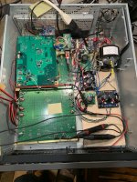
Because things are pretty slow here today, a pic below showing most of the current state of the AK4499 eval board. As can be seen, ebay power supplies work great for everything (except Vref). Easily beats Topping D90 sound. Vocals are not grainy, nor are cymbals. They sound like whatever is on the CD. The eval board itself is upside down and on the bottom. The large-ish green board on top of it is something I made to run some experiments. Some of the circuitry is on the under side. Having acquired some data, a new experimental board is in the works. The Green/Yellow/Orange ribbon cable running around is my color code for I2C bus.
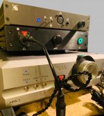
Shown in the second pic is the stack of HPAs used for listening tests. There are two SOA or near-SOA units from Neurochrome, and one Pass Labs HPA-1. They all sound different. Top and bottom ones are my favorites, with the top one getting most of the use by me. When Jam comes over to listen he likes to use the Pass HPA-1, which he knows very well (being the designer of it).
Shown in the second pic is the stack of HPAs used for listening tests. There are two SOA or near-SOA units from Neurochrome, and one Pass Labs HPA-1. They all sound different. Top and bottom ones are my favorites, with the top one getting most of the use by me. When Jam comes over to listen he likes to use the Pass HPA-1, which he knows very well (being the designer of it).
Attachments
Last edited:
Hi Daniel,
Is black pcb an balanced out opamp output stage
can you please give details
can this be purchased online
Is black pcb an balanced out opamp output stage
can you please give details
can this be purchased online
Hi.
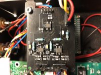
Just solder my PCB (not so Nice
I think it’s a big improvment from the orginal voltage mode anyway.
BR//Daniel
Hi.
Just solder my PCB (not so Nice
I think it’s a big improvment from the orginal voltage mode anyway.
BR//Daniel
Does it has LPF for the 1st stage?
Hello,
Here is the Gerber file for the PCB i use in my dac.
It's from the schematic in post #3003, except that it doesn't have the unbalanced output.
Works for me but can't say for sure that's a correct PCB. And layout are for sure not optimized.
But a nice improvment over the voltage mode OP that are on the orginal dac pcb...
Reason for R13-R16 is throug hole (i put a SMD 1206 in parallel) is that i couldn't find smd parts.
So if anyone want to build this pcb choose either R13-R16 or R20-R23.
D1 and R19 is also an option, i use it to see that dac was on.
BR // Daniel
Attachments
...Maybe i can try to uppland gerber file later.
Daniel,
May I ask what program you used to create the gerbers? If we could look at the source files in the same program then it might be possible to make a few improvements. Hard to say for sure though. Just looking at the gerbers in a gerber viewer is pretty limited.
Last edited:
- Home
- Source & Line
- Digital Line Level
- ES9038Q2M Board