I didnt use an RC snubber, the distortion was familiar from using the transformer with the sabre DAC so dont think there is much that could change.
My vague understanding of delta sigma DACs is that they first interpolate the PCM data to higher sample rate and then a DS modulator reduces bit depth and increase sample rate further. With a 1 bit DS modulator the output wouldnt be essentially DSD?
The AKM block diagram shows these stages, similarly HQPlayer has options for oversampling filter and modulator with a DSD output.
Now AFAIK these newer DACs are multibit DS DACs, it isnt easy finding info on differences between multibit and single bit DS DACs, there is a lot of overlap and confusion. ''multibit'' almost always leads to information on >16bit DACs compared to DS DACs, these >16bit DACs are almost described as ''R2R'' too when non R2R DACs like TDA1387 exist.
Eventually learning how to do some basic programming of a DAC would be great, better to leave till the DAC gets a stronger DIY following and there is more of an audience who can benefit.
I never understood the use of the SRC,
The idea was a one stop shop to solve jitter and clocking issues. It certainly
worked very well, just look at the number of DAC's out there running a single
100MHz clock.
The original ASRC concept was discussed here briefly by Dustin and the
measurements were very good. Then they decided to amalgamate the ASRC
into the DAC.
Gordon Rankin (Wavelength) was the first to run Sabre sans ASRC in sync mode and note the improvement. The rest is history. It took a little time for
people around here to catch on.
if the DAC essentially converts to DSD already. the idea with pre-conversion to DSD was using powerful PC processor to run more complex filter and modulator algorithms.
The DAC is limited in its processing power and cant see how SRC would be any different, is that off the mark?
The PCM side of the DAC is much more complex than native DSD. There are
all sorts of things going on.
IME I think a transformer would bottleneck the Ak4499.
I found 1:4 transformer distortion unacceptable with 9038Pro DAC with little improvement over just a resistor, the 9038Pro did not like anything but op amps for I/V.
Yep, as I speculated in my first reply. It's a balancing act that may or may
not work. The trnasformer quality is paramount.
What sort of transformer did you use?
If using only a resistor for I/V for AK4499 does not give acceptable performance then I think with a trafo either the ratio will be too low to be effective or the distortion will be too high.
The TDA1387 worked decently with resistor I/V and that trafo happened to be a better match for it. However with TDA1387 paralleling chips and lowering the I/V resistor reduced the positive effects from the trafo step up, at 20 or so chips the DAC sounded better with just a resistor than with the trafo, at that point trafo distortion was greater and more offensive. The TDA1387 sounded its best like that, even OPA1612 I/V couldnt compare.
More than likely the 4499 will be the same as 9038Pro, but they arent identical so who knows.
TDA1387 has true current out. I don't know what the voltage compliance is
but the best option for it would be a grounded base, open loop I-V.
T
TDA1387 has true current out. I don't know what the voltage compliance is
but the best option for it would be a grounded base, open loop I-V.
Tried that in various guises - transformer sounds better. In particular the difference is that along with the transformer comes a much greater apparent quantity of low frequency ambience. That is on recordings that have it. It could be as a result of the inherent noise reduction of paralleling devices, I've not tried a trafo with a single TDA1387, I generally use upwards of a few dozen.
Output transformers for DACsWhat sort of transformer did you use?
I have gone through a few of the measurements and they are a mixed bag.
The ES9038Q2M results are not the best. Even at 1kHz there is a lot of
distortion and the noise floor is very high. There are also many harmonic spikes past the 5th, maybe this is a consequence of running Sabre in voltage
mode, not sure.
If your DAC had similar results then I can understand your POV.
These trafos were really good value and also had some reassurance they were suited to this particular application which is the worry with Lundahls or similar trafos, it was the only realistic entry point into transformers for me but perhaps it also tainted my view of them.
I used 9038Pro with HPs so there was a lot of current to play with on the DAC output. Generally going as low possible with resistor value on secondary was best but there was lower limit where sound started to deteriorate, another balancing act to consider for the trafo possibly?
Having to accept unwanted volume at the potential cost of improved DAC performance was the most frustrating aspect of those trafos paired with the 9038Pro.
Well I've been busy with work but managed to spare an evening to do some mods to my board. I'd built an opamp regulated supply on a piece of breadboard but took the opportunity to make use of the opamp and pads on the mainboard so I desoldered all the unnecessary components, cut a few lines and now I have quite a neat opamp regulated supply, just a couple of wires running underneath to the 47uf caps on the AVCC feed. All the other necessary power sources have been replaced, just leaving the onboard 7805/1117 to power the Atmel and inputs.
I still need to solder two LT1763 with the necessary caps to the underneath so I can separate the some of the shared power sources.
I have my pair of +/- 15v Salas BIB powering my Twisted Pair Ivy and the opamp regulator and the 7805.
A separate 7v BiB powers the 3045s regulator providing my 3.3s, I'm in two minds whether to replace the 7805 with the BIB reduced to 5v and use this to feed the board but also the 5v supply to the 3.3v 3045s.
It's almost time to reintroduce the AK4137 SRC although I do need to understand what power supply/circuit improvements can be made to this.
Another question to ask, I need to install a USB XMOS/Amanero board, what do I need to look for? How important are the onboard crystals?
Another question to ask, I need to install a USB XMOS/Amanero board, what do I need to look for? How important are the onboard crystals?
Good to hear of your progress so far
")
Regarding XMOS/Amanero, I am currently recommending JLsounds I2SoverUSB. Jitter is very low which can matter if you decide to try synchronous mode with the dac and or if you want to get DPLL bandwidth setting as low a possible (for best sound quality).
Amanero also makes a good USB board, but the clock frequencies are half what is available from JLsounds. That would be okay except if you wanted to try ES9038Q2M in synchronous mode. In that case you would want the higher clock frequencies to be available.
Both the above mentioned USB boards include ASIO drivers, something necessary for using native DSD in Windows. Strongly recommended the above boards on that basis.
Regarding AK4137, that gets a bit complicated and I don't have a simple answer at the moment although I would like there to be one. Suggest we discuss those issues separately. That discussion would probably also apply, at least in part, to using ES9038Q2M in synchronous mode.
Good to hear of your progress so far
Regarding XMOS/Amanero, I am currently recommending JLsounds I2SoverUSB. Jitter is very low which can matter if you decide to try synchronous mode with the dac and or if you want to get DPLL bandwidth setting as low a possible (for best sound quality).
Amanero also makes a good USB board, but the clock frequencies are half what is available from JLsounds. That would be okay except if you wanted to try ES9038Q2M in synchronous mode. In that case you would want the higher clock frequencies to be available.
Both the above mentioned USB boards include ASIO drivers, something necessary for using native DSD in Windows. Strongly recommended the above boards on that basis.
Regarding AK4137, that gets a bit complicated and I don't have a simple answer at the moment although I would like there to be one. Suggest we discuss those issues separately. That discussion would probably also apply, at least in part, to using ES9038Q2M in synchronous mode.
Thanks Mark, on your recommendation I've ordered the JLsounds board, hopefully shouldn't take too long to arrive being on 'this' side of the pond.
Before I undertake the LT1763 solder to the back plane, are the cap values that Analog suggest sufficient for this, is there anything else I need to consider? Should I use LT3045 or LT1763 for digital (or vice versa)?
For the AK4137 I'll give it a clean 5v, I've got a spare secondary with plenty of 5v PSUs to choose from and if necessary a NewClassD 5v reg so I should have that covered....until mods can be worked out.
For LT1763, probably wise to follow the advice in the data sheet on choice of input, output, and noise suppression caps.
Whether LT1763 or LT304x would be better may depend more on layout rather than regulator data sheet specifications. It helps for regulators powering HF/RF circuits to be dedicated to particular loads, located very near the load, and be mounted on the same ground plane as the load (in order to minimize ground inductance and or noise effects).
What might be best for you may depend a lot on your experience/skill at fabrication using small parts.
Regarding AK4137 board power, I used a Chinese LT3042 (with pass transistor) board as a +5v digital supply pre-regulator. AK4137 was powered by that since there are secondary 3.3v regulators on the board, just as there are on the dac board.
One thing I did find when using one LT3042 board to power all digital board functions is that a ground loop was formed between the +5v ground returns from the dac board and the AK4137 combined with the I2S ground connections between the two boards. Some I2S ground return RF was apparently flowing between the two boards through the +5v power grounds rather than the I2S connection grounds, and that caused some audible degradation of sound quality.
What I did to verify and correct the problem was add some cable clamp ferrites on one of the power supply ground returns to the 5v supply. Adjust the number and size of the ferrites for best sound quality.
As an alternative to that I probably could have used two transformer windings and two LT304x regulators to independently power the dac board and the AK4137 board. Then I2S ground currents might stay where they are wanted and not go where they are not wanted.
For best primary to secondary transformer isolation of low voltage circuits, I found R-core transformers to work best.
Also, probably no reason to use New Class-D regulators for digital loads. I use LDOs for digital loads and other types of regulators for analog loads, say, such as for output stage opamps. Right now I like LT1083 or LT1086 type regulators for opamps, but they are positive regulators only. To use them for + and - rails requires there to be two separate 15v transformer windings rather than one 30v center-tapped winding. With separate windings then a dual regulator board can be used, maybe such as: LT1083 HIFI Linear Power Supply Dual Output High Adjustable Power Supply Board | eBay
However, since LT1083 regulators, and other good sounding analog stage regulators, tend not to be super high gain error-amp regulators they don't fully eliminate all power supply ripple in one stage. For that reason it can help to use two stage regulators and or one or two-stage RC filters before the regulators. LC filters don't usually sound as good. If using multiple regulator stages it can be helpful to use transformers with maybe 20v or 22v secondary windings. Then some voltage can be dropped across the primary regulator and a little more voltage dropped across the secondary regulator. It all depends on what lengths one is willing to go to in order to get the best sound quality.
Last edited:
For LT1763, probably wise to follow the advice in the data sheet on choice of input, output, and noise suppression caps.
Whether LT1763 or LT304x would be better may depend more on layout rather than regulator data sheet specifications. It helps for regulators powering HF/RF circuits to be dedicated to particular loads, located very near the load, and be mounted on the same ground plane as the load (in order to minimize ground inductance and or noise effects).
What might be best for you may depend a lot on your experience/skill at fabrication using small parts.
Looking at the job in hand, it shouldn't be too difficult, I'm going to be using some small 100v Wima MKSs. For the clock, there's already a 106C (10uf) tantalum cap in place, should I leave this or replace with a better quality electrolytic?
Markw4 said:Regarding AK4137 board power, I used a Chinese LT3042 (with pass transistor) board as a +5v digital supply pre-regulator. AK4137 was powered by that since there are secondary 3.3v regulators on the board, just as there are on the dac board.
I have one of these, a useful board to have.
Markw4 said:One thing I did find when using one LT3042 board to power all digital board functions is that a ground loop was formed between the +5v ground returns from the dac board and the AK4137 combined with the I2S ground connections between the two boards. Some I2S RF was apparently flowing between the two boards through the +5v power grounds rather than the I2S connection grounds, and that caused some audible degradation of sound quality.
What I did to verify and correct the problem was add some cable clamp ferrites on one of the power supply ground returns to the 5v supply. Adjust the number and size of the ferrites for best sound quality.
As an alternative to that I probably could have used two transformer windings and two LT304x regulators to independently power the dac board and the AK4137 board. Then I2S ground currents might stay where they are wanted and not go where they are not wanted.
That's really interesting to know, it's been a while since I had the board connected up, I did have that powered separately (using the NewClassD at the time).
Markw4 said:However, since LT1083 regulators, and other good sounding analog stage regulators, tend not to be super high gain error-amp regulators they don't fully eliminate all power supply ripple in one stage. For that reason it can help to use two stage regulators and or one or two-stage RC filters before the regulators. LC filters don't usually sound as good. If using multiple regulator stages it can be helpful to use transformers with maybe 20v or 22v secondary windings. Then some voltage can be dropped across the primary regulator and a little more voltage dropped across the secondary regulator. It all depends on what lengths one is willing to go to in order to get the best sound quality.
This really interested me when you mentioned it earlier on the thread, this coupled with providing more voltage and not relying on the minimum needed for the LDO. For the LT3045s I have, they are powered by my Salas running at 7v, this has sufficient power for the LT1763s when I mount them.
Space-wise, I'm struggling, so using a R-Core with 2x15v and 2x6/9v might be worth considering.
An externally hosted image should be here but it was not working when we last tested it.
An externally hosted image should be here but it was not working when we last tested it.
An externally hosted image should be here but it was not working when we last tested it.
Last edited:
For the clock, there's already a 106C (10uf) tantalum cap in place, should I leave this or replace with a better quality electrolytic?
The caps and other components that come with the dac board (except for the ES9038Q2M chip) are all very cheap parts. I found that the ceramic caps were pretty piezoelectric (probably not X7R). Up to you what you want to do though. The compromised quality of components that come with the board is not as big a problem as the circuit design. That is to say, the dac really needs proper AVCC supplies and a 3-opamp output stage. If those things are being fixed, then it might make sense to fix other things too.
I stumbled over Vivo Xplay 6 smartphone with ES9038Q2M inside.
Measurements:Soomal - vivo Xplay 6 Review: Audio - Soomal.com
Measurements:Soomal - vivo Xplay 6 Review: Audio - Soomal.com
The caps and other components that come with the dac board (except for the ES9038Q2M chip) are all very cheap parts. I found that the ceramic caps were pretty piezoelectric (probably not X7R). Up to you what you want to do though. The compromised quality of components that come with the board is not as big a problem as the circuit design. That is to say, the dac really needs proper AVCC supplies and a 3-opamp output stage. If those things are being fixed, then it might make sense to fix other things too.
Thanks Mark, having 'dumped' the output stage in favour of the offboard Twisted Pair, implemented an op-amp AVCC and moved all of the other DAC power supplies to a mix of LT1763 (next stage) and LT3045 there really isn't much left. Once I start to use the IIS route in from the AK4137 and 'remove' the onboard inputs this leaves 11 SMDs surrounding the DAC and the crystal.
I must get the Arduino connected!
Have I made a mistake by removing the inductors whilst finding a point on the PCB for soldering the new power source?
The inductors are presumably there to minimize noise from loads from getting into the power supply rails and adversely affecting other loads, and or possibly affecting performance of the voltage regulator.
Once dedicated regulators are available for each load then its not clear if there would be reason for keeping the inductors. Might do more good to remove them. Hard to know for sure without trying it both ways.
Hi! Just fired up my highly modded 1.07 board and I cant get it to work. Only the display fires up.. I have a few questions regarding the operation of the board.
1. Are the input jumpers necessary when using the rotary switch?
2. Is the optical plugn'n play ?
3. Can I use the original inputs together with the IIS from a Amanero board?
4. Does the Amanero board board work with this 1.07 card straight away?
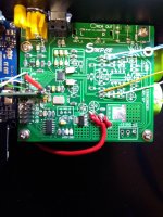
I also attached a picture of my board. The AVCC gets power from underneath the board(LiFe 3.3V) through the stock electrolytic cap pin holes. If anyone finds any mistakes on the board please let me know. All the new regulators measures 3.3V. Is there any way to find out if the dac chip is fried? Thanks for any help!
1. Are the input jumpers necessary when using the rotary switch?
2. Is the optical plugn'n play ?
3. Can I use the original inputs together with the IIS from a Amanero board?
4. Does the Amanero board board work with this 1.07 card straight away?
I also attached a picture of my board. The AVCC gets power from underneath the board(LiFe 3.3V) through the stock electrolytic cap pin holes. If anyone finds any mistakes on the board please let me know. All the new regulators measures 3.3V. Is there any way to find out if the dac chip is fried? Thanks for any help!
Attachments
1. Are the input jumpers necessary when using the rotary switch?
Shouldn't be needed, except J1 and J2 installed at the same time may lock up the controller so don't do that unless you mean to.
2. Is the optical plugn'n play ?
Don't know myself about that if the display is hooked up. If the display is disconnected then IIRC J1 selects optical input.
3. Can I use the original inputs together with the IIS from a Amanero board?
Yes. Amanero or other I2S source can be connected while SPDIF and or TOSLINK is connected. Jumpers J1 and J1 select which input will be used if the display is disconnected.
4. Does the Amanero board board work with this 1.07 card straight away?
Depends where you bought the Amanero board from. Twisted Pear flashes the firmware for use with external clocks. If you buy directly from Amanero then the firmware uses the clocks on the Amanero board.
If it is a Chinese Amanero clone it uses its own clocks, but can't be flashed with new Amanero firmware or it will become bricked.
I also attached a picture of my board.
Picture is a little blurry. Hard to say much about it.
[/QUOTE]
Is there any way to find out if the dac chip is fried?
[/QUOTE]
An oscilloscope would help greatly with determining that. Otherwise, no real way to tell if the dac clock is working, or what input signals may be present.
Make sure you have an output stage powered up.
You might try removing the display and disconnecting any volume pot, just to keep things simple. Then use J1, J2 to select I2S or another input. Before starting playback you should see Vref DC voltage on all the dac outputs and I/V output pins. When you start playback some AC voltage should start to appear on I/V output pins (which would be the audio).
Thanks for for the help Mark!
I now managed to get it to work! It was a combination of my optical on my pc not playing along and a cut trace to the inputs. It worked right away on dvd player I first tried before finding the cut trace. It turns out the optical is plug'n play, havent tried the other inputs yet. So theoretically my chinese Amanero board should work native? Is there any leds on the Amanero btw? Do know of any good treads on the Amanero board?
I now managed to get it to work!
It was a combination of my optical on my pc not playing along and a cut trace to the inputs. It worked right away on dvd player I first tried before finding the cut trace. It turns out the optical is plug'n play, havent tried the other inputs yet. So theoretically my chinese Amanero board should work native? Is there any leds on the Amanero btw? Do know of any good treads on the Amanero board?Chinese Amanero boards should work fine for PCM audio. If using Windows OS, then appropriate precautions should be taken to minimize added distortion caused by Windows Sound Engine. Please let me know if you need info on that topic.
Otherwise, there is not much one needs to know about Amanero boards except the pinout for I2S. Official Amanero data sheet shows that info: https://www.amanero.com/drivers/combo384-D.pdf
All you need are DATA, BCLK, LRCK and Ground.
Sometimes different names may be used for the signals, for example FSCLK is the same as LRCK (Frame Sync Clock is the same thing as Left/Right Clock).
CLK and DCLK are same as BCLK (Data Clock is same as Bit Clock).
EDIT: Amanero drivers may be be needed for Windows to recognize the device. They can possibly be downloaded from Amanero or you can ask the Chinese seller you bought from to provide drivers (which may be best). However, ASIO and native DSD won't work with the Chinese firmware. Only way around that is to get a better USB board. The recommended one is I2SoverUSB: I2SoverUSB - I2S over USB Audio
Last edited:
- Home
- Source & Line
- Digital Line Level
- ES9038Q2M Board